Find us on Google+ Inventor Tales

Thursday, September 11, 2008

Autodesk Manufacturing Academy


As part of my new home at Ketiv, I'll be at the Autodesk Manufacturing Academy in Cerritos on September 25th!

The events going to be a full day of Manufacturing based courses including Inventor, Data Management, and AutoCAD Electrical.

Feel free to check it out by clicking here! I hope to see you there!

Monday, September 08, 2008

Inventor CAM - The next Adventure!

Part of my new tech journey is venturing into the world of CAM (Computer Aided Manufacturing).

Hence, here I sit with InventorCAM on my system. Working with programming CNC machines using InventorCAM.

I'm still pretty early in the process, so think of this as the 'preview for the movie', but so far I'm pretty excited.

Look for a few more blogs in this regard as I travel further into a whole new world!

Thursday, September 04, 2008

Hello KETIV! - Time for a Change

Sometimes it just becomes time to move on.

After a long and difficult decision making process, I've moved on, and joined KETIV Technologies in Fullerton.

I'm looking forward to the new opportunity where I'll begin to learn CAM (Computer Aided Manufacturing) technology as well as continuing to develop my skills in Inventor, Vault, and Productstream.

Since you've located me here, you can also see that I've changed my blog address to the current one (http://www.inventor-tales.blogspot.com/).

I plan to keep blogging from this address once I get settled in to the new place, so feel free to bookmark it and take a visit back.

P.S.
Here's the website for my new home! http://www.ketivtech.com/

Tuesday, August 05, 2008

Properties in a BOM

Finally! I have a chance to put something a little more substantial in the blog. It's been hectic, so I'm afraid I haven't been able to put more than a 'blurb' (that's a technical term) in here.

I was asked a little while ago how to get properties into a Bill of Materials, but in the format of 'length X width X Thickness' look.

Now, a chance to document it!

So here we go.

First, a picture of the part I'll be using for this portion of the blog. I've circled the dimensions I'm going to work with.


The first thing you need to do, is rename the variables in your parameters screen, and name them something that is a little more sensible than the Inventor issued variable names. (Okay this isn't REALLY necessary, but it'll make life easier).


Once this is finished, go to File>I-Properties and create a custom variable with the following format. = X X The format is important. This combines all the variables on one line. Like before, you need to remember the name of this variable (you'll need it later).


Click 'Add' followed by the 'Apply' button and the value will enter and update. Note the 'fx' symbol next to the property, indicating that the value is driven by parameters.


Now, we configure the drawing!

First we've got a drawing with the part, and the Bill of Materials placed, but we still need to add our new property.

First we edit the BOM (right click on the BOM and hit 'Edit Parts List' and go to our 'Column Chooser'


Once in the Column Chooser, create a New Property, and enter the name you entered in the I-Properties.


Hit OK (a few times) to close all your dialog boxes. The property will show up in the BOM, and now you can adjust the formatting until you have the look you want.


The other advantage of this particular method, is if your part changes, the parts list will also update as well.

Happy Inventing everyone!


Friday, July 18, 2008

Following the I-Map

From the depths of Autodesk Labs comes up yet another tool.

I-Map for Inventor.

This, in my humble opinion, may be one of the best technology previews yet. There's a lot of potential in this one!

The Link for I-map is here.

I-Map let's you create a map of constraints and shows which parts the constraints are acting on.

The picture attached below shows an example of how constraint mapping works. It's like a flow chart for constraints (at least that's how my little brain views it). Click on the picture to enlarge.


The other option is Skeletal I-maps, which also let you see features and exported parameters.


When you install I-Map, you can access the tools by right clicking in the modeling window (Note it's got to be the modeling window for the assembly you intend to map!)


The constraint maps open up in a second window, so you can toggle between the two by using your Windows Pulldown in Inventor.

I-Map also gives you a new shortcut on your desktop to start it. So you always have the option of starting Inventor without it if you choose.

Happy Inventing everyone!

Monday, June 16, 2008

Autodesk Labs Preview - Vista-ize your Inventor

There are those of us who like to live life on the edge. I for example, was running Windows Vista and Office 2007 before SP1 was even out.

Don't even think I can be stopped, I'm a man on the edge!

Now, the Inventor UI preview is available for download from Autodesk Labs, located here.

The screen capture below is an example of some of the changes.


By installing it, you have the option to get the new 'Ribbon' features similar to what you would get in the Office 2007 products.

My personal view, after some 'seat time' with Office 2007, I've grown to like the interface myself. After a few minutes working with Inventor's new UI preview, I think I'll like it too once I'm accustomed to it.

And don't worry, there is a safety net. When you install the preview there are two icons to start Inventor, one with the old UI, the other with the new UI.


If you choose to try it, have fun!

Friday, May 30, 2008

Selecting Text issue with Word 2007 and Vista

They say that being the pioneer means you have to catch all the arrows.

This was the Vista adventure a couple of days ago.

Vista installed some updates for me (that's right, it didn't ask me first), and after that Word's functionality got 'interesting'.

I tried to edit my Word document, and I couldn't select any of my text with the mouse! I use the arrow keys and edit my document the (very) hard way, but the mouse cursor would just float over the top of the words like they weren't there.

After grumbling and complaining to my laptop, I decided to do a Google search, and found the following solution.

http://support.microsoft.com/default.aspx?scid=kb;en-us;940791

It does involve a registry edit (albeit an easy one), but as always, be cautious and backup your registry.

After doing this, the problem went away!

Happy Friday!

Thursday, May 29, 2008

Adding more fields to Vault (because there's never enough!)

I recently was asked how do I add fields to my Vault file list.

It's actually much easier than you realize, once you know where to look.

Here's the fields that I currently have shown in my file preview.


My next step is to go ahead and add a new one. First, all I have to do is right click on the title bar.

This brings up the 'Customize Field' dialog box, where I can choose the fields I want to add or remove. Note that you may have make sure the pulldown in the upper left is set to 'All File Fields', if it's set to 'Frequently Used Fields', it may be blank (since no fields may have been used frequently in your case)!

Once this is done, hit okay, and the new field will appear (or the ones removed will disappear). In the example below, I used the 'Add' button to insert a 'Last Write' field (circled).

Hope this is helpful!

Thursday, May 22, 2008

Keeping Yourself, or at Least Your Gravity, Centered

One of the nice 'subtle but significant' new features in Inventor R2009 is the ability to add a center of gravity marker to your drawing.

In this example, I'm going to show the COG (center of gravity) symbol on the fixture shown here:


I'm starting out with a view of a simple jig, but we want to show the COG for this asssembly. Here's a picture, although we'll actually show the COG in the top view.

Here's the steps.

1) In the browser, locate the part or assembly where you want to show your COG.


2) Right click on the assembly of interest, and choose the 'Center of Gravity' option.


3) That's it! the COG will be shown on your view! You can also place dimensions on it so you know exactly where it is!

Tuesday, May 06, 2008

Changing Your View (Cube)

It's been a while since I've posted, and again, it's been hectic.

But here's at least one of those 'little things' that I've noticed poking around in Inventor.

When you're using the view cube (which I've been practicing with), you can use it to orbit too.

If you click anywhere on the cube and drag, you can orbit your part without having to go to the icon, or your F4 key.


Happy Inventing!

Monday, March 31, 2008

R2009 A different View

Time for the first 'what's new' in R2009.

The first thing is the view cube, which is located in the upper right of the screen (although it can be turned off). If you click on the picture below, you can see it indicated in the red circle.


Pretty much the same tool as in the DWF Viewer, it supercedes the 'glass box'. By clicking on different portions of the box, you can rotate your view to look at the model from different angles.

At first, this fell into the 'Well, that's cool, but I'll never use it' category. Especially since I'm using a Space Traveller from 3D Connexion (www.3Dconnexion.com).

Well, that perspective changed pretty quickly. After spending a couple of hours using it, I found that I was using it quite a bit more, particularly for looking straight down at narrow edges (especially sheet metal).

So much for that first impression. I think I'll be using this quite a bit more than I initially expected!

One last note! The 'Isometric View' is now called 'Home View'. Not a big change, but it might through you off a bit the first couple of times.

We'll see what a little more seat time shows!

Tuesday, March 25, 2008

It's that time again!

Yes, it's that time of year again!

The 2009 releases are here! I'll be trying to point out as much of the new stuff as I can in the next couple of weeks, but it's going to be a rush to take it all in!

Feel free to take a look at the Autodesk website here!

Specifically, the Inventor what's new is here.
AutoCAD Electrical is here
.

Tuesday, March 18, 2008

I get by with a little help from my friends.

Yes, as I quoted the Beatles on this one. I guess that means I'm getting old. :-)

As I'm working some new tips (it has been a little crazy lately), I wanted to mention that I've added a link to a new Inventor/AutoCAD Electrical/Data Management blog on my links section.

Among the other Blogs, please check out Steve McCarthy's Cadgneto blog here!

Feel free to bookmark it, or just pick it from the 'blogs' section of the page!

And feel free to cruise by some of the other blogs on that section!

Friday, March 07, 2008

It's not copying, it's 'reverse engineering'.

Today, I'm putting out a Vault tip that everyone may find useful. Copy Design.

Copy design is a way of taking an assembly, and all the parts and drawings that go with it, then reusing the parts that are reused, and making copies of parts that are new.

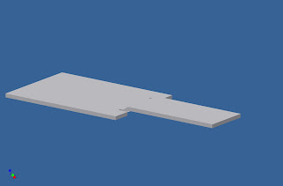
For this example, we have a part for a wood coffee table that needs to have a section cut from it (referred to as a 'Cloud Lift')


However, from previous designs, we know that there's a jig that already does this for a different part.


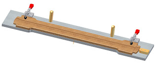
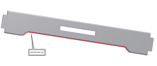
The basic jig is the same, we're using the same clamps, handles, and stops. But the base of the jig (where the router bit will actually ride), will need to be shortened for the new jig, since the part it's cutting is shorter than the current one.

Here lays the rub. We're still making this stretcher, so the current jig must remain available.

Here's where copy design can help.

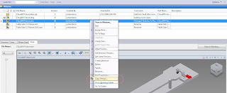
First open Vault Explorer. Then locate your jig (cleverly named 'Cloudlift Fixture'). Right click on it, and choose 'Copy Design'

Once Copy Design comes up, you can choose which parts you want to reuse (designated by the yell0w '+' symbol), or which you want to copy (designated by the Cyan '++' symbol).


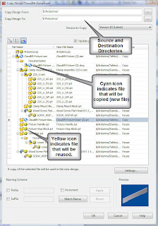
In this case, I'm copying the assembly file, the base, and any drawings that go with it. Once I've done this, I click OK.

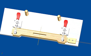
Once this is finished, I can go edit the new assembly in Inventor, and make the changes I need.

In this case, I shortened the base to fit the new part, moved the clamps and handles to the correct position, then updated the drawings.

The good news, I didn't have recreate any of the assembly, or create any new drawing files (although I did have to create a couple of new views for the design).


The second jig took about half the time to create than the first (maybe even less, but I wasn't very scientific in my tracking).

Still, it can be a huge help in reusing data, preventing duplicate files, and reducing the chance for errors (and lost time), down the road.

Happy Friday!

Monday, February 11, 2008

Using Your Design View in a Drawing

So last time I talked about creating a design view, but here's a little about how to put one in a drawing.

I have two covers, a blue and a green one (you might recognize these from the last blog on this).


Now I'm going to put these into a drawing, but continue to reference the views.

1) Create your base views like you would normally, but now choose the design view that has the assembly you want. I'm choosing the assembly with the Blue cover. Also, I'm going to associate the drawing view to the design view.


Now, I have a view of a blue cover on my drawing.


Of course now, comes the inevitable 'so what', and I don't blame you, but here's where the little used 'Associative' check box can help.

Now, I can go back to my assembly, and change the color of my view, I'm going to choose Cyan. Don't forget to unlock the view first!


Now lock your view again, and switch back to the drawing.


The drawing view will also be cyan. I know this may not be a big deal on smaller drawings, but if you're creating larger drawings (particularly some where the drawing views are used to show color changes), this can help document the drawings a great deal.

Happy Inventing, I'm already thinking of the next thing to blog!

Sunday, February 10, 2008

New Tech for the Home Shop

Sitting at home today, I was watching T.V. in between checking my eyelids for light leaks (in other words, I was napping), and caught a comercial for, of all things, a what amounts to a CNC router for the home shop.

It's not too extravagant, but looks like it would do most things a hobbyist would want! At $1800 U.S., it's not cheap, but it's also something that's in the realm of the hobbyist.

I guess it's another case where technology is working it's way down to the masses. Here's a link.

I'm working on putting another Inventor blog up! I'm thinking about one that talks about putting design views into drawings, so stay tuned!

Friday, January 25, 2008

Why do you backup files?

I guess you can call this a Public Service Announcement.

This actually happened, a disgruntled employee at a firm actually deleted years worth of files!

If this isn't reason for a good backup, I don't know what is!

Here's the article!

Wednesday, January 23, 2008

It's all in the way you (design) view it

One of the often overlooked parts of Inventor (at least in my opinion), is Design Views, AKA View Representations.

Using Design Views can be a great way to make switching between different views in your assembly.

A Design View remembers three things about your assembly.

1) The camera angle
2) The color scheme
3) Part visibility

The advantage is, it remembers them, so you don't have to!

For the first step, I'm showing an assembly in the same way we'd always look at it.

Notice where I've indicated the design views (these are the defaults in any file).


However, we're going to create a couple of other things we're going to turn off the black tabs hanging off the part, change the color of the yellow part to red, and look at it from a different angle.

For our first step, we 'pose the assembly'. In other words, create your desired result, just like you would normally would in any Inventor Assembly


Now the tabs are gone, and the colors been changed. We've also rotated the part.

But how to we get Inventor to 'memorize the view'?

1) Right click on the 'View' in the browser, as shown below, to create a new design view.


2) Once you do this, a view with a default name will appear. You can double click on the name in the browser, and rename it to something that makes more sense than 'View1'.


3) Believe it or not, the view's just been created! There is one more step to make sure that your view is ready to go. Right click on the name one more time, and lock the view. This will make sure that any parts that are added to the assembly don't appear in your design view when you don't want them to!

4) Once this is done, you can create other views by repeating the steps.


Happy Inventing!

Friday, January 18, 2008

A few quick websites.

Finally! The first post of 2008! I started out the year by taking a snowboarding vacation to Mammoth, and the rest of the time catching up from being at Mammoth! :-)

For starters, I just wanted to post some websites that I find helpful from time to time. You may know a few, and a few may be new.

I'm thinking about some new stuff to put up, so I should have some more material soon!

www.sdotson.com (free tutorials)
www.cbliss.com (free parts downloads)
www.engineersedge.com (A site with engineering formulas and standards)
www.matweb.com (A site that has the properties of several materials)

www.contentwarehouse.part-solutions.com/PARTcommunity/Portal/autodesk (Autodesk content site, powered byPARTsolutions)

I hope these are helpful!

As for me, here I am in Mammoth! Good news! All my extremities came back in working order!


Monday, December 24, 2007

Going Out for a Joggle

Merry Xmas everyone! As I'm sitting here making my final preps for the holiday, I thought I'd put in a blog I've been intending to do for a while.

Joggles.

I've been ask a few times how to do them, and they are in there. Here's how you can do them.

1. I'm starting with a sheet metal face already created, and we'll add a joggle to that. Start by creating a sketch on the face where you want the joggle to be. (Click on the image to see a larger version).


2. Create your sketch, make sure you're colinear to an edge.


3. Create another face. But this time click on the edge button, select edge you want your joggle to start from. Make sure you set it to 45 degrees. You can use your offset to define the orientation of the joggle.


Voila! Happy Holidays!


Take this Christmas Icon
Christmas Icons
Myspace Icons