Find us on Google+ Inventor Tales

Wednesday, March 25, 2009

Inventor R2010 - Ribbons! We Don't Want No Stinkin' Ribbons!

So now we're sitting with Inventor R2010, and the first thing you'll likely notice is the interface. I refer to it as 'Vista-ized', since with Windows Vista, we started seen the ribbons in Microsoft Office.

Last year AutoCAD went to this format in R2009. Even Snagit, which I use to take the screen captures you seen in this blog has gone to the ribbon.

Now, it's Inventor's turn.

For my part, I like the ribbon. I've gotten used to it, and once I got over that hump, it liked what they did. But for me to say that I didn't struggle with a learning curve would definitely be an exaggeration.

So if we need to go back to the 'Classic UI', here's how you do it.

First, bring up your Application Options

Now you'll see you applications screen, which is much like the same old one we saw before. Switch to the colors tab, and change from 'Ribbon UI' to 'Classic UI'.


Once you hit either 'Apply' or 'Close', Inventor will prompt you to close and restart.

Once you restart, Inventor R2010 will open up in the same layout we're used to seeing. Once you're ready to switch to the new interface, just repeat the steps and you can return to the Ribbon UI.

Enjoy everyone!

Tuesday, March 24, 2009

2010 is here (at least for Inventor)

I take a week off in Mammoth and what happens! Inventor 2010 ships when I get back. But, in a lot of ways, it's like Christmas in March for geeks like me! :-)

I haven't had a chance to start playing around with it like I want to, but believe me, I'll be installing it as soon as I get my little hands on it!

You can start reading up HERE!

Look for some what's new posts soon.

As for me, I almost got snowed in at Mammoth! Here's a picture of my truck shortly before I started digging it out.

I also need to extend a thanks to Giro. I took one heck of a wallop on my (helmeted by Giro) head. Rung my bell enough to give me a 2 day headache and send me to the doctor for a checkup.

Fortunately, they said I'll be fine (at least what qualifies for me as fine)!

All I can say is that I just became the worlds biggest fan of Snowboard helmets!

Here's one more picture. It's me at the Mammoth Summit. It's 11,053 ft. Trust me, I got winded putting my bindings on!

Sunday, March 15, 2009

Showcase and Mammoth Mountain..

So here I am at Mammoth Mountain. I'm relaxing and getting ready for my first day of snowboarding.

And yes, I'm blogging. Just tally that one up to being a geek.

Here's a quick tip before I cash in for the night.

This week I did a lot of work on Showcase, so here's a quick reference on Showcase.

I decided to share one of the tricks, but, since I'm in Mammoth, and I'm going to be vacationing. This is just a quick one.

Using Handles on a part.

When you have a part in Showcase, you can translate, rotate, and scale the part inside Showcase. See in the picture below I've selected a part, then hit the 'H' key to display the handles.

By using the handles, you can perform several actions on the part.

1) Click and drag along X,Y,Z arrows on the handles to translate.

2) Click and drag on the curved heads to rotate

3) Click and drag on the box next to the X,Y,Z arrows to scale allong that axis.

4) Click and drag on the center box to scale universally

5) Click ang drag on the plane to translate on that plane.


If you click on the head of one of the arrows (translation or rotation), you'll also get a dialog box that lets you enter a value.


That's the big stuff right now. I may post a picture or two from the trip up here. Just because this is one of my favorite places to visit.

Happy Inventing, while I'm vacationing I may post a picture or two of what's up here in Mammoth. It's definitely one of my favorite places to be!

Tuesday, March 03, 2009

(I) Logically Speaking, it Makes Sense

Lately, one of my treks through the Inventor world has been into iLogic, the rules based functionality that Autodesk rolled out to Inventor subscription customers.

It's been a very unique experience, mostly because it's been entirely brand new.

For those of us who aren't familiar with iLogic, picture being able to enforce rules and automate with simple lines of code. It's a way of capturing knowledge that extends beyond the dimensions and constraints of the model.

As I've been practicing, I created a quick example.

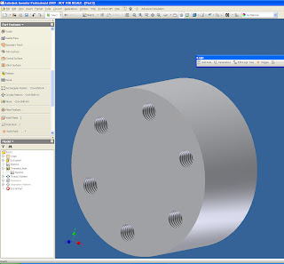
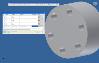
I just built a small part with threaded holes, and a matching pattern. I'm going to write some iLogic code that alternates suppressing the threaded and clearance holes together. However, we'll change it by selecting a pulldown from the iLogic parameters screen.

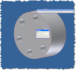
Here's our starting point. If you click on the picture, you can see the clearance and threaded holes (I renamed the features. This will help me in writing the code later).

First, click on the 'Parameters' button on the iLogic toolbar.

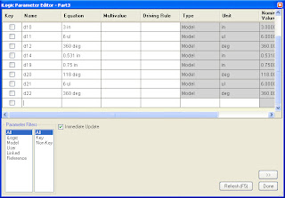
This is what the Parameters screen will look like initially.

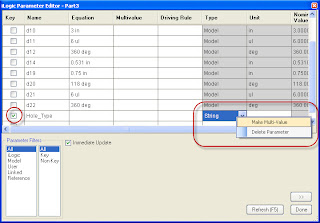
Create a parameter named Hole_Type, use the pulldown (circled) to make the parameter a string, check the 'Key' check box, and finally, right click and choose 'Multi-Value' (this makes the parameter a list of selections).

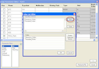
Once the parameter is set to 'Multi-Value', a second parameter comes up. Type in the Clearance_Holes, and Threaded_Holes into the screen and click 'Add'. You can type as many entries as you need, but for the sake of simplicity, I'm only using two.


I hit 'OK', and the box closes. We'll use this later. Now I click on 'Add Rule'. I chose to name mine 'Hole Suppression'. Hit 'OK' to close this particular rule.

.

Now, we get down to the real business of iLogic, writing the code that controls the features. The code is written in the area indicated, and the 'Rules Syntax' tab provides a wizard to help you with the syntax of the commands.

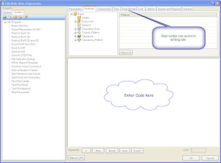
Here's a the code I created. You can type it, double click on code in the 'Rules Syntax' area, use the buttons at the bottom of the screen, or use any combination of the three. If you have a line of code that's already similar, you can even use copy and paste commands.

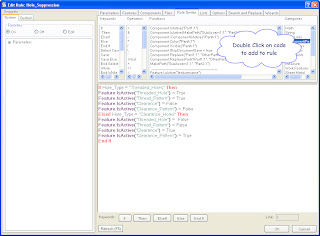
The code in the window controls the suppression. Here's a quick key of what the code does.

If Hole_Type = "Threaded_Holes" Then ==> If the mutli-value is set to "Threaded_Holes" then...

Feature.IsActive("Threaded_Hole") = True
Feature.IsActive("Thread_Pattern") = True
Feature.IsActive("Clearance") = False
Feature.IsActive("Clearance_Pattern") = False ==> This code sets the Threaded Holes to calculate, but suppresses the clearance holes

Elseif Hole_Type = "Clearance_Holes" Then ==> States that if the 'Hole_Type' Parameter is set to "Clearance_Holes" Then..


Feature.IsActive("Threaded_Hole") = False Feature.IsActive("Thread_Pattern") = False Feature.IsActive("Clearance") = True Feature.IsActive("Clearance_Pattern") = True ==> This group of code inverts the previous section. This is a great place to use that copy and paste I was talking about!

End If Tells iLogic we've got all the selections we need.

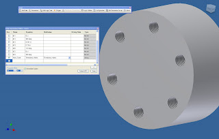
With that finished, we can return to the iLogic parameters and change our multi-value settings. Now the rule controls the selection.


One final note. The first thing you might say (as a matter of fact, I did too), is 'I can use I-parts for that'. You'd be right of course. I-parts can do exactly this. So why go throught he effort of writing this code, even if it is simple?

I think this really comes into play for templates. IYou can easily create new parts from these, and not have to worry about things like proxy files that I-parts require. iLogic grants a level of flexibilty that I-parts aren't able to easily achieve, especially when the configurations get more complex.

Don't get me wrong, I think I-parts are a great tool. For things like library parts, I think they're a great solution, and I'll happily use them in that capacity.

So that's the first in many things. Look for more info as I go deeper into this, and my other, worlds.


Saturday, February 28, 2009

More on Filters! Making Selections Easier.

Just this Friday, someone asked me how you could quickly edit a part in a sub assembly without going through the multiple edits required to get to edit the sub, then the part, then the feature, etc.

As a result, I created this video showing an example of how it might work.

I hope everyone finds it helpful.

Bear with me, I've now upgraded to Camtasia for videos. So far, it's proven to be a great tool, but I have a ton to learn about it!

Saturday, February 21, 2009

How Do You Like Your Part List? Filtered, or Unfiltered?

Things have been busy lately. There are days that I feel like I should put that in the fine print. But then again, I don't have any fine print. :-)

This time, I thought I'd mention something that's new to Inventor 2009, but may still not have received the fame it deserves.

Parts list filters.

The part list filters (like their name implies) filters the items visible in the parts list by the following criteria:

  • Assembly View Representation (Design views for those of us who remember that far)
  • Ballooned Items Only
  • Item Number Range
  • Purchased Items (Designated in the Assembly BOM)
  • Standard Content (i.e. Content Center Components)

For this example, I'm going to use the 'Ballooned Items Only' option.

At the start, I have the parts list placed on our sheet. I've ballooned the parts I want to show on this view and placed my parts list.


But the parts list shows all the components in this assembly, and while this may be desirable in some circumstances. This isn't one of those cases.

In order to rectify this efficiently, I'm going to right click on my parts list, and choose the 'Edit Parts List' option.

Once in the parts list, choose the Filter Settings button.

The Filters Settings dialog box pops up, and now you can choose your options, and set your filter. Click the green check to commit it, or the red 'X' to remove it (in case you make a mistake). For this case, I'm choosing Ballooned Items.

Once the options are selected, choose OK and close the box down.

While still in the part list editor, you can already see the effect of the filter.

Hit OK again, and the parts list will update to reflect the filters you've created. That's it!

P.S. if you add a new balloon, the part list will update automatically to add the item you've ballooned.

In other news. The first announcements for what's new in the Autodesk Manufacturing Solutions has arrived. Click here to check it out!

Happy Inventing!

Friday, February 13, 2009

All right, Mr. DeMille, I'm ready for my close-up.

When we last left our Showcase hero (that's me, BTW) on February 3rd, we had imported our clamp into a scene, but had yet to do much else to it.

In this blog, we're going to create an environment that's going ad a bit more of the realism we're looking for.

So with our clamp brought into Showcase, the first step to get away from that default blue screen is to go to our Scene>Environment Pulldown.


Once we select Environments, the tree with our available environments will appear.

Next, we left click on the environment we want, and add it to our scene. It will move from our environment library (the lower row) to our environments in scene (top row). It won't appear yet, however.

Now we can click on the Environment in the scene. It now becomes active, and we see that our part is now sitting on a wood floor, sort of. Our part is 'buried' in the floor, and we have to make one last adjustment.

To resolve this, go to the Scene pulldown again, and choose 'Set Floor Position'.

With this option open, now you can move the slider up and down to adjust the position of the part on the scene. You can also use the 'Move to Bottom of Model' option. This may not work every time (it does depend on the origin on which the model was originally built at), but it can position the model quickly.


With the positioning completed (by one method or another), you can return to the Scene>Environment option and turn off your environment menu to complete the scene.

Add a few more some shadows, and you're heading down the road of a Showcase scene.

I've also embedded a video of changing between scenes. I'm slowly getting better at this Youtube thing, but I still have a way to go. Thanks for being patient!


More to come later! It's getting late and I need to sleep sometime!


Tuesday, February 03, 2009

Video Killed the Radio Star...

If you know where that title comes from, you're dating yourself (right along with me, by the way).

But it seemed appropriate given the fact that I've officially published my first Youtube video. It's a preview of some of the new Rules Based Design Technology that's being shown in Inventor.

The video's not as nice as I'd like it to be, but it's my first go of it after all. I'm hoping to do a couple of more, and get them better!

Thursday, January 29, 2009

Win, Place, and Show(case)

This is the ongoing story of a mechanical brain slowly making his adventures in the more artistic world of Showcase.

At long last, my engineer's mind has past the point of 'plastic deformation'. You designers and engineers know what I mean. My mind is being stretched past the point where it will no longer snap back to its original limits.

So with the philosophy out of the way, I've been working (at least as much as time will allow), with bringing my Inventor files into Showcase.

As I mentioned in the last blog, the process starts with a 3D model (In my case, it was Inventor, but could be another CAD program).

The first step is to import the model into Showcase using one of the detail options.

Trying to keep things short, here are the steps involved

1. Go to File>Import Models

2. Select your file, and open it. You'll be asked to choose the level of detail that you intend to use.

This isn't the same as the Level of Detail in Inventor (which unloads components from memory). This controls the tessellation (how many facets) the solid uses. The lower the detail, the 'blockier' the solids look. However, they load faster. The higher the detail, the better they look, however, they will load more slowly.


Once you choose your Level of Detail, you can bring in the components by hitting OK. You'll see the import progress screen come up.


3. This completes the import. You're now ready to start applying environments, materials, transforms, and shadows.


Ultimately, you can end up with this:


I'm going to add more to this in further blogs, but in the upcoming weeks, expect to see,

  • Putting the model in an environment
  • Choosing materials
  • Using transforms to orient the model
  • Creating ambient shadows
On a final note, both myself, and my esteemed colleagues at KETIV (Nicole, Mike, Javier, and Jonathan C.) are holding web events in February and March on the following subjects, all at no charge. Please feel free to swing by and take a look. We'd love to see you there.

  • iDesign: Intelligent, Features, Parts, and Assemblies (Inventor)
  • Get More From Your Autodesk Subscription (All disciplines)
  • Building Custom Componenets - AutoCAD Electrical
  • Large Assembly Management (Inventor)
  • AutoCAD Customization (AutoCAD)
  • Showcase Your 3D Designs (Showcase)
  • InventorCAM: Powerful CAM Functionality (InventorCAM)
  • The Missing Link - File Projects in Inventor
  • Sheet Set Manager (AutoCAD)
  • Unleash the Spreadsheets (AutoCAD Electrical)
You can register here

Happy Inventing! Or perhaps it should be 'showing' in this 'case' (get it? 'Showing' 'Case' = Showcase).

Bad puns aside, good weekend to everyone!

Wednesday, January 28, 2009

Never use the default password.


I'm in the middle of putting a new Showcase blog together, but I've been pretty busy, so it's not quite ready.

In the meantime, he's a little bit of a PSA (Public Service Announcement), on why you should probably change your default password on, well, just about anything.

This is an actual article off of Foxnews, right here.

So the next time you think of letting the default password slide, think of Austin, Texas.

As for that Showcase post, look for it toward the end of the week!

Friday, January 16, 2009

Making What Works Look Good Too (Autodesk Showcase)


One of my new adventures in 2009 is Autodesk Showcase, and while a grip of fun, has been challenging too.

First of all, what is Showcase anyway, and what does it do?

Showcase is a rendering tool that allows you to take 3D CAD models (even non-Inventor models!) and not only create photo-realistic renderings of them, but will also give you the ability to change colors, camera angles, and visibility in real time. You can literally see what your design is going to look like before it's even left your computer.

So what is the challenge for me?

I'm a mechanical engineer by degree. By definition that makes me the guy who things in a Cartesian coordinate system of X.Y.Z, with a tolerance of plus or minus .005.

Now for the Showcase world, where you hear things like 'that looks better if you move it a smidge'.

What the heck is a 'smidge' anyway? Is that some sort of constant that wasn't in my Dynamic Systems Analysis Course? I don't remember that one!

After deciding a smidge was smaller than a 'nudge' and bigger than a 'little bit', I carried on.

Things are a bit more subjective in the Showcase world, but once I shelved my '+/- .005
brain, I began to see what was possible.

I would have loved to have had this back in the days when I was designing enclosure hardware. It would have saved us days in presentations and trying to make SLA prototypes look real. Not to mention the catalog work we could have gotten done without having to build prototypes for photoshoots!

But the past is the past.

And this is the grips of fun part... making something that works... look good too.

There's a lot that can be talked about in Showcase, so I'll keep the basic steps concise. I thought that before I went in and started talking about 'tips and tricks', I'd just show the basic steps to get from CAD model, to rendering As I 'blog' on, I'll get into more depth in the steps and show you some of the things I get to work on!

First, you import your model


Next, get your model oriented.


Next, apply your materials and insert it into a scene.


With a scene and materials done, you can now calculate the ambient shadows. Once the materials and scene are in, you now have a rendering that you can rotate, modify etc!

True enough, there are subtleties, nuances, and tricks that you can use to make things look even better. It's also true that this is a pretty condensed process described here, but I'll add more soon. I promise!

Happy Friday everyone!

Friday, January 09, 2009

Editing your Dimension Styles Faster!

So, here it is 2009, and I'm still wondering where 2008 went. It seems I was snowboarding in Mammoth only six months ago, now I'm planning the next trip!

Here's a tip I ran across that I sometimes forget myself.

Working with dimension styles can be a little tedious at times. But there's one little thing that has definitely made it a little easier.

Most of us who've been using Inventor for a while know the standard method to editing dimension styles.

That is go to the Format>Styles and Standards pulldown menu, locate the dimension style, and either modify it, or use it to create a new one.


Of course, that brings up the Styles and Standards Editor. While powerful, this can be a pretty intimidating to identify and change the correct dimension style.


Thankfully, there's a way to get to the correct dimension style with a little less headache.

Just choose a dimension that you want to modify or copy, and right click on it.

By choosing 'Edit Dimension Style' you can modify the existing dimension style, changing all the dimensions it affects.


By choosing 'New Dimension Style' you can copy an existing dimension style and alter the copy to create more dimension styles.


These have the advantages of dropping you right into the correct dimension style when you're editing. In the case of creating a new dimension style, you can choose an existing dimension style that most closely suits your desire, and use the 'New Dimension Style' to make a copy you can modify.

Happy 2009 everyone! I hope this proves to be another helpful tip.