Find us on Google+ Inventor Tales

Sunday, April 14, 2013

Linking Parameters from One Part to Another in Autodesk Inventor

“New links must be forged as old ones rust”
Jane Howard

Last week, I was asked "Can you link parameters from one part to another in Inventor?" 

I had to think back a bit.  It's been several years since I had used this method, but in short, yes it can be done, and this is how to do it.

First, I have two parts, a shaft, and a base that contains a bore shown in an assembly file.  The shaft has a dimension that may vary, but I know the corresponding bore has to be .025 larger than the shaft.  I'm purposefully keeping the clearance large so the change is easier to see.

 Looking at the image below, it's easy to tell that the clearance is far larger than .025.  I'll use parameters to like the diameter of the bore to the diameter of the shaft.


The shaft and bore.  The dimensions are unlinked.

The first step to perform is to edit the shaft part, and rename the parameters that define the shaft diameter.  This step isn't really necessary, but it does make the parameters easier to work with.  I'm also going to check the "Export Parameter" check box.

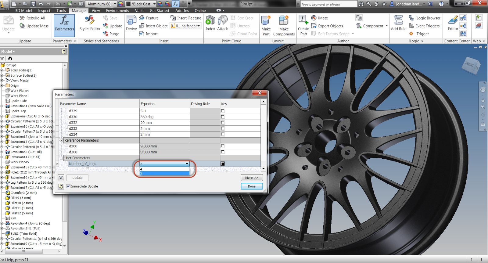
Parameters are located on the "Manage" tab. 

Preparing the Parameter for use.
With the shaft parameters prepared, finish editing the shaft, and start editing the base.   Edit the parameters for this component as well.  Note that the parameter for the hole diameter has already been given a unique name.

Showing the parameters for the bore.
The first step to linking the two files together is to click on the "Link" button.

The "Link" button is in the lower left of the parameters box.
This will cause the Open dialog box to appear.  Change the file type from Excel files, to Inventor files.  I'll select the Shaft.ipt part, and click "Open".

Opening the file to link.

The Link Parameters dialog appears, this is where the parameters to be linked can be selected.  Although multiple parameters can be selected, in this case, only the parameter Shaft_Dia needs to be selected.  Click on the icon so a yellow "+" symbol appears.


Selecting the parameters to link

Clicking "OK", the parameter will be linked into the file containing the bore.  The parameter will appear in gray, at the bottom of the parameters dialog box.


The parameters are added.

Now, an equation can be built using this parameter, adding the clearance of .025 inches.  The image below shows the equation created in the parameters dialog box.

The equation created.

 Closing the dialog box will reveal that the bore as already sized according to the new equation that's been added.  In the image below, the assembly has been sectioned, and the shaft made flush with the bore to make the gap more visible.

The gap added.
The real strength of this method, is when the shaft is re-sized.  Since the shaft and bore diameters are linked, the dimension of the shaft will change the diameter of the bore, while maintaining the clearance!

First changing the size of the shaft.

Changing the parameter. The shaft has already updated.
Finishing the component edit will reveal that the bore has updated while maintaining the clearance.

The bore re-sized.

This application can be very helpful in dynamic designs where component dimensions are going to change often, and a little bit of "light automation" can be helpful. 

Where is that case to be found?  That's up to you! 

For a video showing the steps used above, look below! In my video, I used .015 inches for the clearance.  But the ideas are still the same!


Sunday, April 07, 2013

Using Autodesk 360 to Create an Interactive View on a Webpage

“A pessimist only sees the dark side of the clouds, and mopes; a philosopher sees both sides and shrugs; an optimist doesn't see the clouds at all--he's walking on them.”
Leonard L. Levinson

Sometimes, the most interesting and unique things happen completely by accident.  And I'm going to discuss an instance of that here.

Over the last few months, I've been delving deeper into the use of my Autodesk 360 site, and exploring it's capabilities a little more deeply.

And there's a lot that can be done.  It can store files, it can control who has permissions to view and download files, it can be used to run, analysis, simulation, and rendering projects, as well as product life cycle management.   It can even be used as an online view for someone who needs to see your data.


In this post, I talk about a subtle capability that can add a lot of bang for the buck.  Embedding a viewable dwf file in a website.

A 3D dwf can do a lot to help make a design to life.  The viewer can zoom rotate, pan, and interact with the file.  These capabilities can add a lot of clarity, and value, to a proposal, or to the evolution of a design process.


So how can you create the embedded code into a webpage, like I've done above?

First, create a dwf from the source file.  In my example, I'm using a dwf of the 4 sided die I created a few months ago. 


Once the dwf is exported, switch to your Autodesk 360 account, and prepare to upload the file to the account.  In my example, I've created a folder called "Blog Shares".  But you can name the folder anything you want.  It's not necessary to create a folder, but I prefer to.  It helps organize things


Browsing into this folder, I'll go ahead and select "Upload" to begin the process of selecting and uploading the file.

 This opens up the window to browse to the file to upload.  Files can be dragged and dropped, or folder browsing can be used to add the files.  Multiple files can be added using this method as well.


In this case, I'm only adding one file, so I'll select it, and hit the "Upload Now" button.


The file will upload, and after a few minutes, the dwf file will generate it's view.  However, it's completely locked down, and nobody but the person who created it can see it.


In order to share the file, I'm going to move my cursor over the dwfx file.  I'll see icons for a Preview, Assign Categories, Actions, and Add Comments.

I'll select "Actions", choose "Sharing", and then choose "Public Sharing"


A dialog box will appear where Public Sharing can be turned on.  A link is created where the file can be downloaded, e-mailed, previewed, and finally, embedded.

Choosing "Embed", Autodesk 360 creates html code that can be used to copy and paste into a webpage (like this one!) and create the embedded preview above


So that's how Autodesk 360 can help amp up your website.  If you haven't checked out Autodesk 360 yet, it's worth taking a look at.  You get 3GB of storage just for starting it up!

One thing to note, I did edit the code to make the view fit better on my page.  But that's the only alteration I made.

And for the video version of this, take a look at that embedded file below!

<iframe width="545" height="409" src="http://www.youtube.com/embed/4vculzWL_dI" frameborder="0" allowfullscreen></iframe>


Friday, April 05, 2013

Working for the Weekend & Going to the (Content) Library

“A library is a repository of medicine for the mind”
Greek proverb 

I'm occasionally asked where additional content center libraries can be found for Autodesk Inventor's Frame Generator, and it seems those are not easy things to come by.

I suspect that's because of the time involved in creating them, once someone invest the time to make one, they're reluctant to just give them away.   But do I know for sure?  No. I don't.

But a few weeks ago, I was walking the virtual isles of the file sharing site GrabCAD, and low and behold, what do I find?  Inventor Content Center Libraries for 8020 extrusion!  The files were created and uploaded by Stan Wile, and he deserves a big thanks for sharing the work he's created.

A sample of the extrusions use to create a frame. I've turned off one of the extrusions for clarity

The files are in *idcl (Inventor Desktop Content Library) format, and here's how they can be made available to your installation of Autodesk Inventor 2013.  Once those files are downloaded, it's time to get started.

First go to Tools>Application Options>Content Center Tab, and find the location where the Desktop Content Center is located.


The Content Library locations.

Now go to this location, and paste the *.idcl files into this location.  The other Desktop Content Libraries will be here.


The 8020 library placed into the Desktop Content Center location

But there are a couple of more steps before everything is ready to go.

The libraries have to be made available to the project using the libraries.  To start this step, go to the Application icon (I call this the "Big I"), and choose Manage>Projects

Navigating to the project file location


Once the Projects dialog box appears, click on the "Configure Content Center" icon at the lower right of the dialog box, just above the "Done" button.

Configuring the Content Center Libraries
Another dialog box comes up and the library can be added to this project by checking the box next to the 8020 library.

Adding the library to the project

Now, the 8020 extrusions can be used just like any frame generator component.

Using the new extrusions

If you want to download and add these extrusions to your own installation of Inventor, you can download them from GrabCAD by clicking here.  Yes, there is a membership required, but once you get into GrabCAD, I think you'll like a lot of the things it has to offer.

Also, if you're using a version of Inventor earlier than 2013, all is not lost.  Stan has also provided the 3D models of the profiles, which can be used to create your own Content Library by using the instructions at the Autodesk link here.

A Final Note

The libraries provided are for Inventor's Desktop Content.  If you're using Autodesk Vault, and wish to move the files to the Vault Content Center Libraries.  They can be transferred by using the Library Transfer Guide to be placed into the Vault Content Center Library.

Accessing the Library Transfer Guide


Tuesday, April 02, 2013

Using iLogic to Change Threads in Components... From the Assembly!

“Words form the thread on which we string our experiences.”
 Aldous Huxley

Not that long ago, I was tasked with a unique challenge. 

Trying to change threads using iLogic.  And while I knew it was possible, there was an additional twist. 

I had to do it from the assembly.   Now that's a way to add a wrinkle or two!

How do I change the threads in each component from the assembly?

 So I hit my favorite search engine, Google, and started surfing away.


And low and behold, I found my solution in the Autodesk Wikihelp, diving so deep I needed a diving bell. 

Torn from the Autodesk Wikihelp, the rule I need!

With a little testing, and verifying, I was quickly able to get this little gem to work.  The biggest thing I like about this version, is it allows for the changing to different thread types.  Such as from Metric, to Imperial. 

Using this method, I was able to set my threads from the assembly, without having to drill down into each part. 

In this example, I'm changing from a coarse thread to a fine thread, but with a little more work, I could expand this rule to do a lot more, and have it controlling much more than just coarse to fine.

Each "Feature.SetThread" command calls to the component in the following method:
"Bore :1"    ==>  This is the component being called out
"Threaded Hole"     ==>   This is the name of the feature being called
"ANSI Unified Screw Threads"         ==>   The thread type.  Basically, the tab in the Thread.xls chart.
"3/4-10 UNC"    ==>   The thread designation
"3B"   ==>   The thread class

Below is the full rule changing the threads for both the components in the assembly.

If Thread_Type = "Coarse" Then
'Callout for Bore
Feature.SetThread("Bore :1", "Threaded Hole", "ANSI Unified Screw Threads", "3/4-10 UNC", "3B")
'Callout for Shaft
Feature.SetThread("Shaft:1", "Threaded Shaft", "ANSI Unified Screw Threads", "3/4-10 UNC", "3A")

ElseIf Thread_Type = "Fine" Then
'Callout for Bore
Feature.SetThread("Bore :1", "Threaded Hole", "ANSI Unified Screw Threads", "3/4-16 UNF", "3B")
'Callout for Shaft
Feature.SetThread("Shaft:1", "Threaded Shaft", "ANSI Unified Screw Threads", "3/4-16 UNF", "3A")

End If


Now, with a multi-value list set in Parameters, I can use this small ilogic rule to change the threads for me!

Here's the rule setting coarse threads.  Notice the callout in the assembly browser.


The rule setting coarse threads

Now the rule is changing the threads to fine threads.  Now see how the callouts have changed to find in the assembly browser.


Now with fine threads, all changed by the rule.

That's it!  I hope you find this tip helpful!  And if you'd like to download the files I used in this example, you can download them from my Autodesk 360 site here!


Sunday, March 31, 2013

Points for Style - Quickly Adding an Insert Constraint in an Autodesk Inventor Assembly

“We are not constrained by capital, but by opportunities as we grow,”
Jeremy Bentham

There have been times that I've had to place a whole bunch of insert constraints in  quick succession.  And while Inventor tools do allow for the pretty quick placement of constraints like this. 

Here I have one of the textbook we've used in our training classes in the past.  It has six bolts that have to be placed into their holes by using the insert constraint.


Six bolts might be a lot to put in.  Is there a faster way than the "standard" process
That method, is the Alt+Drag method of creating constraints, an alternate way of creating constraints without directly activating the constraints tool.

To use the Alt+Drag method, I hold down the "Alt" key, and left click on the first circular edge I want to apply the constraint to. 

Picking my first circular edge to apply my constraint to.
Next, while still holding down the Alt + left mouse button, I can drag the bolt to the second circular edge.  The hole I wish to place it into.


The constraint being applied as the bolt is dragged into place


Now, all I have to do is lift the left mouse button, and the constraint will apply.  I've never had to click on the Constrain Tool.

With that constraint placed, I can quickly use the Alt+Drag method to apply insert constraints to the other bolts, nuts, etc in the assembly.  Until I've placed all the fasteners I need. 

All the bolts placed


And for a video showing the steps, take a look below!


I really like using Alt+Drag for Insert constraints myself, but that's just a preference of mine.  The  Alt+Drag method can also be used with other constraints, like Mate and Tangent, for example.

The Autodesk Wikihelp has a great video showing the full spectrum of uses HERE.  So feel free to take a look at that to help expand your knowledge even further!


Thursday, March 28, 2013

Keeping up with the Power Curve - 2014 System Requirements for Autodesk Design Suites

I have the power!
He-Man

It looks like Autodesk's 2014 based products are on the horizon.

And while I haven't seen any dates indicating when that's going to be, I've noticed that the system requirements are up on Autodesk's website.

I've noticed that it looks like Windows 8 is getting support, which is good news for many, I'm sure! 

The Product Design Suite Page


So if you're thinking of going to the 2014 based products, and you're interested in seeing if your hardware is up to snuff, check out the link HERE and see if how your hardware stacks up!

Tuesday, March 26, 2013

Looking Forward - The Autodesk 2014 Suites Announcement

“I don't think there's any bigger goal than that one right there, up to this point. It was another highlight reel by our best player. And it just kind of shows the kind of character he has to just take charge like that.”
Steve Rucchin

Earlier today, Autodesk announced the 2014 Suites to the world.  Just in this fairly brief preview, there looks to be a lot of cool things coming down the ways.  It's something I'm looking forward to diving further into as the details come out!

New tools like Recap for laser scanning have my curiosity captured, along with the improved Inventor to Revit interoperability. 

But there is something for all the designers out there.  If you're using Building Design Suites, Factory Design Suites, or Entertainment Design Suites, there's a little something for everyone. 


Before I get to the video, I do have to do a little bit of shameless plugging.  Look for the Sunkist and California Analytical (CAI) in the opening "credits".  They're KETIV customers!  And so are Plastics Research Corporation, and Enviroguard

It's an honor to be a a member of the team involved with helping these companies.  Best of luck to them going forward!

Now to the video! 


Sunday, March 24, 2013

Construction Geometry in Autodesk Inventor - Is it Really Necessary?

“It's a lot in construction and so it's just everywhere.”
David Roberts

Construction geometry in an Autodesk Inventor sketch is one of those topics that doesn't often get talked about.  It's not shiny or flashy, it just sits there and quietly does it's job.

Usually, construction geometry's job is to help position a sketch, or to help apply constraints, such as a symmetry constraint to the sketch. 

The question I pose in this post is, should I change a line's properties such that the line's acts as a construction line in the "Inventor sense"? 


An example of the construction line type in a sketch
I consider using construction geometry a good practice, although "no Inventor police will take you away if you don't do it".  In many cases, little difference might be seen between setting construction geometry, and not setting construction geometry. 

So what is the difference, and why bother setting construction geometry?

Here's a sketch where I've used horizontal and vertical lines to help set position, and symmetry for a sketch. The lines are all standard sketch lines.  No lines have been set to construction.

Notice that all lines are "standard" sketch lines

The first thing that usually gets noticed is when the sketch is extruded into a solid.  The sketch is now cut up into regions, because Inventor sees each line as a potential boundary for the extrusion.  In this case, I have to pick four different regions to extrude this entire sketch.


The sketch broken into regions by its own geometry

Now picking four regions might not be a big deal.  It's just a few extra clicks, right?   But now what if you need to put a draft, or taper angle, on the same solid.


The image below shows the result, since the sketch sees the internal lines as edges for the extrusion, it applies the taper there as well, created the "waffled" solid that might not be the desired result at all.


Internal geometry can change the result of the extrusion
So what happens if I change the properties of the internal geometry to "Construction"?

I'll do that by selecting the geometry I want to change, and clicking the "Construction" icon.  The line types will change to reflect the property change.


The internal lines after being changed to Construction.
But now, when I extrude that sketch, the behavior of the extrusion changes.  First, I don' t have to pick the sketch in quadrants anymore.  That's because the internal lines, set to be construction, are ignored as sketch boundaries.


Now the extrusion can be created in one step.
Secondly, if I need to apply a taper, my result is completely different.  That's also because Inventor doesn't use Construction geometry as boundaries for a feature.  The waffled feature disappears.


With Construction geometry, no waffle!

So there's a little bit on construction geometry, and why it's worth considering.  There might be plenty of places it doesn't matter, but in cases like the above, it can be useful.  I encourage you to take a look.

And of course, here's a video (with my somewhat raspy voice this week) below!


Wednesday, March 20, 2013

Using Capture Current State with Autodesk Inventor iLogic

The photograph itself doesn't interest me. I want only to capture a minute part of reality.
Henri Cartier-Bresson

Recently, I was working on a part where I was controlling the number of features in a pattern using iLogic.  Inevitably, I had to figure out how to take an existing feature, and change some of it's values with iLogic. 

But I didn't remember a lot of the details, like parameter names, or even the exact context for the command. 

Take a look at this automotive rim (it's just a sample file I'm using).   I want to control how many lug holes the rim has. 

This is the rim I'll be working with
Even though I've given custom names to the pattern that controls the number of holes, as well as the parameters driving the pattern, I may not know the names off hand.

I could pull them from the browser in iLogic, but that could be very time consuming if there's a lot of parameters to sift through, and it can mean a lot of scrolling up and down until the parameter is found.

And this is only one parameter, what if there were more? 


The parameter found, after a lot of scrolling up and down, though.

Another way I found that can be extremely helpful is to locate the feature, which even though there's a lot of them here, is easier to locate than a single parameter.  Once the feature is selected, right click on it and choose "Capture Current State".

Notice that I renamed the feature too.  It makes the feature I'm looking for a little easier to find.


Capturing the current state of the feature
Once the state is captured, iLogic gives me information about the current suppression of the feature, as well as grabbing the parameters associated to the features.

The current state captured
 The bonus of this method, is that I can use these values as the basis for creating my rules.  I'll start by adding my If/Then/Elseif statements.

Now, I could turn off my pattern completely if I changed the "True" to "False", like the example below:
Feature.IsActive("Lug Pattern") = False


But in this case, I'm only changing the number of Lug Holes, so I'm going to remove the lines that don't pertain to the number of lugs.

The final rule is shown in the image below:


The finished rule.
Now the rule can be checked, and verified.

4 lugs, check!

5 lugs, check!

Now this rule can be expanded by getting other states, or by using any combination of iLogic techniques.

For more information on creating an iLogic rule.  Check out my post from the archives here.

For some great iLogic resources, check out these blogs by Curtis Waguespack, and Paul Munford!

Sunday, March 17, 2013

No Blog Post this Monday!

Awesome image courtesy of FBCoverstreet.com
Today, I'll be skipping the usual Monday quote due to a birthday holiday.  I turned 40, and crossed into my next decade of life, which I do hope to make the best ever!

Once again, I found myself snowboarding in Mammoth, joined by good friends and having a good time.

It was incredible spring conditions!  And I rode until my legs quit working!

So here's a few pictures, and I'll have a new post coming "techie" post coming up soon!

Riding up the gondola to the top

A gorgeous spring day

A view from the top of one of the chairs.  The views alone are worth it.

The view into the Sierra Nevada range from the summit.  Yosemite and Half Dome can be seen from here!

Wednesday, March 13, 2013

Changing Model Orientation in Autodesk Showcase AFTER it's Imported

“Every orientation presupposes a disorientation.”
Hans Magnus Enzensberger

Last week, my post showed how the orientation of a model could be changed as it was being imported into Autodesk Showcase. (You can check out that post here)

But what if the file has already been imported?  Marion Landry of Autodesk shared a tip via the video comments that pointed it's possible after import too!  It's definitely a valuable little jem of a tool I didn't know was there!

I'm starting out with my model already imported sideways.  So there's no chance for me to fix it using the methods I used in my previous post. 


It's in sideways, and now how to fix it?
But to fix it afterward, all I have to do is go to the File>Import>Import Status Window menu, or just hit the "I" key.


Locating the import status window


Once the Import Status window appears, I'm going to right click on the name of the imported model under "Source Files".  Choose "3D Model Properites.

It's important to right click on the imported , or 3D Model Properties won't appear!


Now, I get the "Original 3D Model Properties" dialog, where I can change the units, and the "Original Up Axis".  Choosing "+Z", the model is reoriented!


So there it is, a quick way of changing orientation after a model is imported.  Thanks to Marion for taking a few minutes to show this valuable tip!