Find us on Google+ Inventor Tales

Sunday, September 22, 2013

Linking AutoCAD Block Properties into Autodesk Vault

“The mind's cross-indexing puts the best librarian to shame.”
Sharon Begley

It's been a busy week this week!  So unfortunately, I haven't had a chance to build videos.  But instead of holding the post back, I'd rather share what I have now.

I'm hoping to build the videos a bit later, and add them in!  In the meantime,  I hope the post below is helpful!  

I recently found myself doing indexing AutoCAD block attributes into Autodesk Vault.  During this process, I thought to myself: "Self, this is probably something that should be documented". 

So I decided to share it here!

First, the "Setup"!

I've created a block with just one attribute in it.  FACILITY NAME.  What I would like to do, is place this file into Vault, and make the facility name a property that can be searched by within Vault.


The first thing I want to do is take note of the block name in Vault. This can can be accomplished in AutoCAD, and selecting block, and using the command BATTMAN (for batch attribute manager, not the Caped Crusader).


Next take note of the attribute tag that's going to be indexed in Vault.

In this case, the tag is named FACILITY_NAME.  This is important for the next step, where Vault is "taught" what information to read from the block.


Now that the tag name is known, it's time to open up the Autodesk Data Management Server Console (ADMS).  Once logged in, select Tools>Index Block Attributes.


Selecting this tool will open up the Index Block Attributes dialog.   Choosing the New button will bring up a dialog where the block name is entered.


Make sure to type it exactly as it appeared in AutoCAD!

Accept and close the dialog boxes.

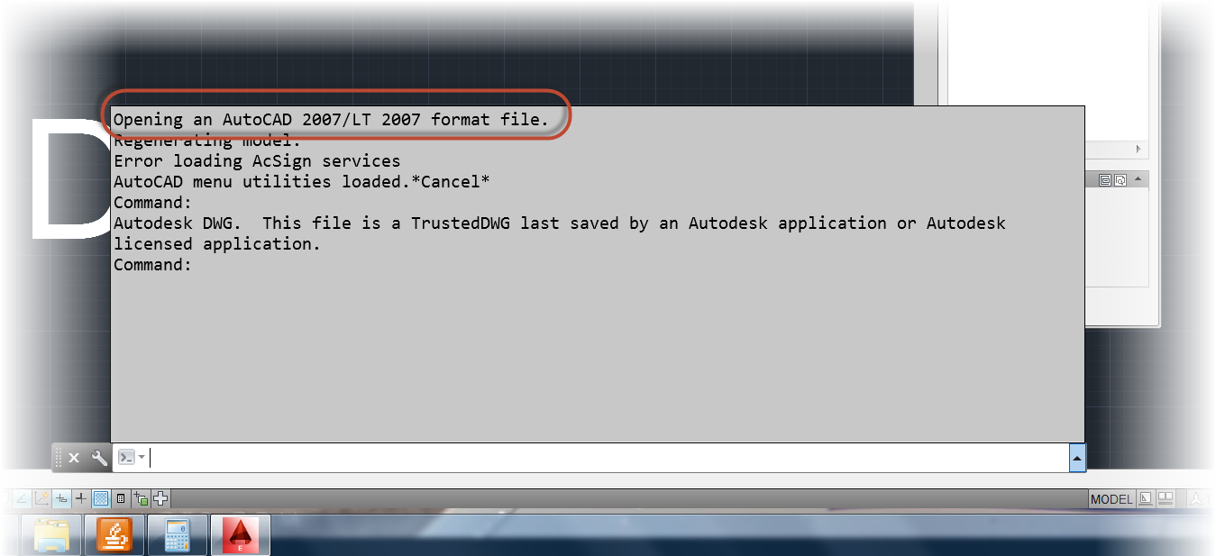
Now, Vault needs to be seeded with a file containing the block to be indexed.  The first step in this process, is to check in the file in Vault.

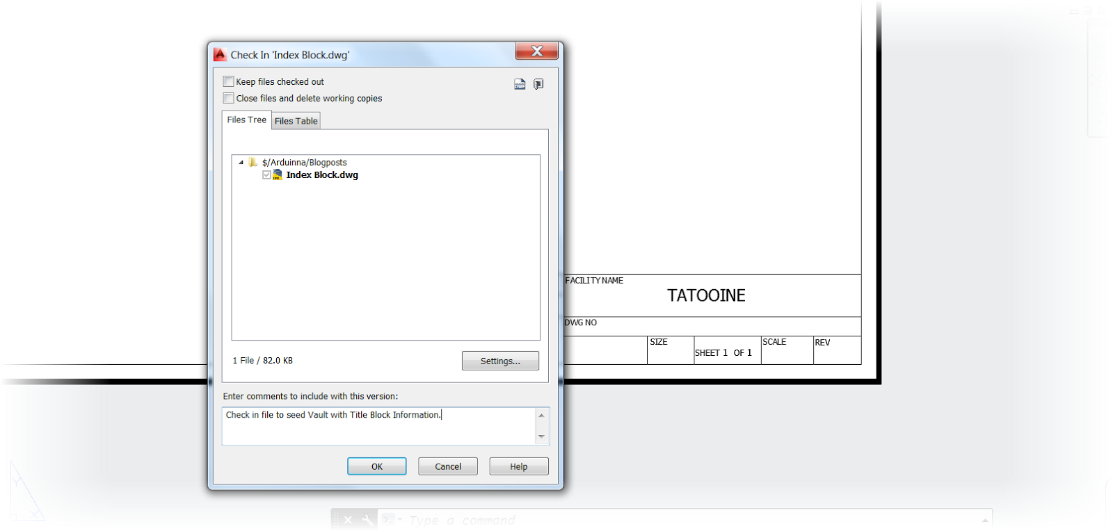
Checking the file into Vault
Now, the "Connection"!

Now with the file checked into Vault, the appropriate property needs to be created and mapped. 

First, go to Tools>Vault Settings.


The Vault Settings dialog box will appear.  Choose Properties from here.


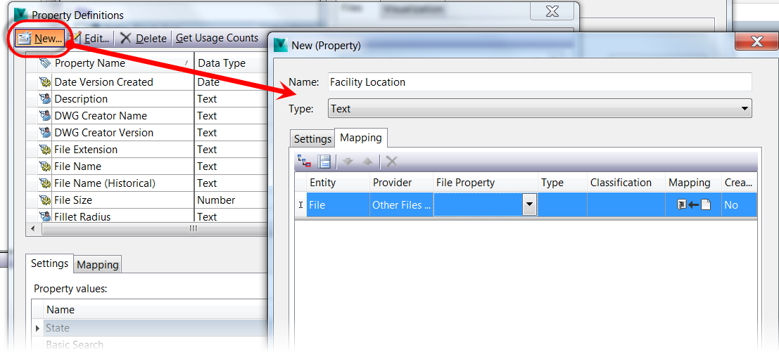
Now, it gets fun!  Click the New button to create a new property.  I'm going to call it "Facility Location".

Add caption
The next part of this step is to map in the actual AutoCAD block property to the Vault Property.  This is where the connection is made.

Click in the empty File Property box to bring up the "Import Properties" button, and choose Import from Vault.  


Now the seed file can be located by browsing in Vault.


The list of properties will appear.  Browsing through the list will yield Title Block Enter Facility Name, which is exactly the property that's needed!


Accept this value and close all the dialog boxes.  There are a few more steps to go, but not too many.

Using Customize View, make the new property in visible in Vault Explorer by right clicking on the title bar in Vault Explorer and choosing Customize View.

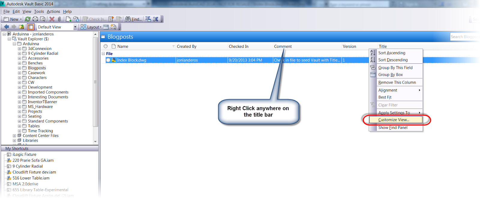
Customizing the view
Now, follow that up by locating the Facility Location property, and moving it to the visible fields panel.  The "Move Up" and "Move Down" buttons can be used to reposition the field if desired.

Accepting this, the field will appear in Vault Explorer, but there's one issue.  It's empty! 

There's one more step left.  Return to the ADMS Console, and select the desired Vault, and choose Re-Index Properties.  This will reread the properties in Vault, including the one just added. 

Note that this process can take a while if there are a lot of files, so give it some time to finish.  If there are a lot of files, it could take over an hour.

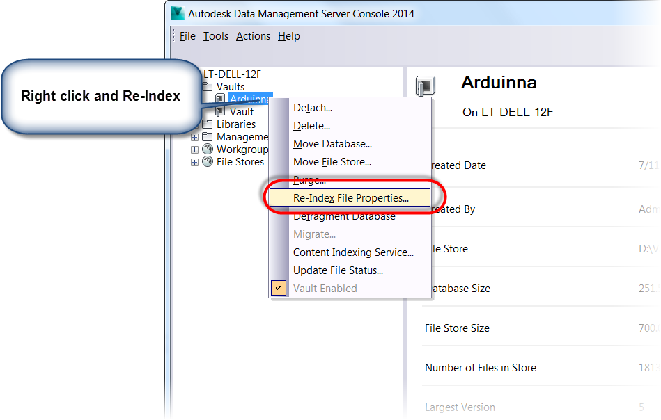
Re-Indexing the properties


Now, after the files have Re-Indexed it's time to return to Vault Explorer and refresh the screen by hitting F5.

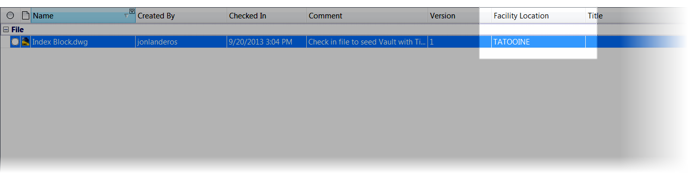
Now the property is visible!

At long last, the process is finished!

I know this seems like a long winded process, and I wouldn't disagree that there are quite a few steps involved.  After all, I just spent hours writing them all out! 

But now that it's done, it's done.  Any additional AutoCAD files that contain this block will populate the fields from this point forward.  So the heavy work is done, now it's time to reap the benefits!


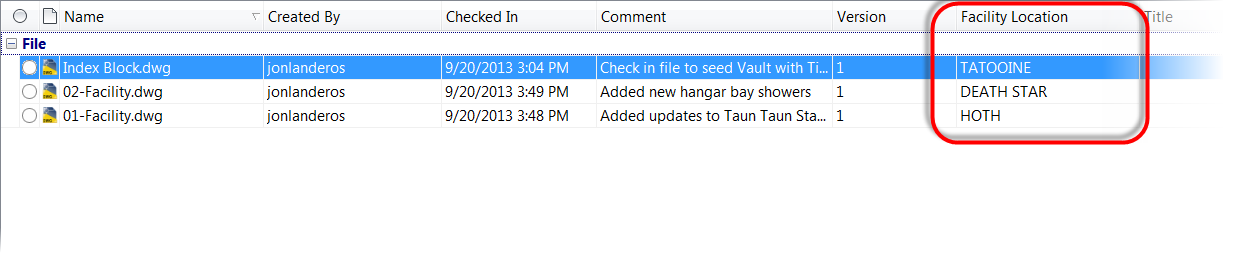
The properties are done!

Give it a try!  It can make a big difference automating those much needed steps!

****************************Edit 13-October-2013************************************

I've added the videos to accompany this blog post!

*****************************************************************************************


Part 1


Part 2


Sunday, September 15, 2013

Which Version of the Truth? An App for Checking DWG Versions

“History is the version of past events that people have decided to agree upon.”
Napoleon Bonaparte

The other day I was asked, "Is there a way to check what version a dwg file was created in?"

I had to think a moment.  I don't work in AutoCAD as much as I used to, so it's safe to say I'm a bit rusty.

But I set off on my quest to take a look, and up popped a couple of methods.

The easy one?  Open the file in AutoCAD.  Once the file is open, hit the "F2" key and you'll see a line that says, "Opening an AutoCAD XXXX format file"

Finding AutoCAD dwg version by hitting F2 immediately after opening


But there's also a more elegant way!

In my searches, I found an application on the Autodesk Exchange App site that will display the DWG version in Windows Explorer!

This app is called DWG Columns for Explorer by JTBWorld, and it creates a column in Windows Explorer that displays what version of AutoCAD the DWG was created in.

The App as it appears on the Autodesk Eschange site


So I downloaded it down, tested it, and found out it's a slick little tool.  It's simple, and it's effective.  Just like many good tools. 


How cool is that? 

So give it a try!  I know it's a nice little app that I'll be keeping on my own machine for a long time!

Note that there's also a pay version that shows all AutoCAD properties.  I haven't given that one a try, but it the pricing looks to be pretty reasonable, so maybe down the road, I'll give it a shot!

If you end up trying the premium version out, leave a comment and tell us all what you thought!

And before I wrap up, I'd like to leave a couple of tips on setup below!

1) Once installed, open up a directory containing dwgs in Windows Explorer.

2) Right click on a column.  If you don't see "DWG Version" choose more.


3) Located "DWG Version" and check the box.  Click OK when done.


4) The column will now appear in Windows Explorer!
 

Thanks for reading this post!  Have a great week!

Tuesday, September 10, 2013

Autodesk Introduces 123D Circuits... For Free!

 My method is different. I do not rush into actual work. When I get a new idea, I start at once building it up in my imagination, and make improvements and operate the device in my mind. When I have gone so far as to embody everything in my invention, every possible improvement I can think of, and when I see no fault anywhere, I put into concrete form the final product of my brain.” 

Nikola Tesla

While looking around at some geeky tech news, I ran across this announcement on TechCrunch from Autodesk.

Autodesk Introduces 123D Circuits. 

123D Circuits is a free online app that allows for the creation and testing of virtual electronic circuits?  Premium accounts are also available.

This really interests me!   As a Mechanical Engineer, most of my experience with electricity comes from the "blue spark" and the tingly feeling that comes afterward.  Sot he ability to learn in a virtual environment (away from real electricity) is really appealing!

Have I checked it out yet?  No.  I haven't had an opportunity, but I think I will be looking at this in the future.  It sounds intriguing indeed!


For more info from the Autodesk Sandbox, take a look here!

And to jump in and get your feet wet, check out this link! I know I will

And for an overview video, take a look at the link below!

Introducing 123D Circuits.io from circuits.io on Vimeo.

Sunday, September 08, 2013

Take Your Best (Animated) Shot in Autodesk Showcase

“Cinema is a matter of what's in the frame and what's out”
Martin Scorsese

In my post last week, I talked about creating static camera shots inside of Autodesk Showcase.

But Showcase can also create animated shots too! 

In these shots, different camera animations can be created that make the camera zoom, orbit, or pan across the object in the scene.

By using these effects, a compelling 'eye catching' scene can be created.  One that will really grab the attention of the intended audience.

So how can a cinematic shot be created?

Just like in my previous post, go to Story>Create Shot.  Options to create an Orbit, or "Start to End" Shot are available. 


Now, the Properties dialog box shows up, and I can begin tweaking my animation to suit the needs for a shot. 

There's a lot of different things that can be tweaked, so I created the image below.


All of these settings can be adjusted to create different types of animations, all giving a different type of effect.

For example:

Motion Type switches the motion between Still, Cinematic, and Start to End. Depending on the type of motion selected, animations for Orbit, Pan, Zoom In/Out, etc. These have the added bonus of being able to capture a point along the camera path to set the view.

Motion Path
controls the path for the camera, creating the desired camera effect for the animation using a point along the path.

Path Dimensions allow the camera path to be adjusted by typing in the angle, position, and duration of the camera path.

By adjusting these settings, the animation can be changed and just like before, mutliple animations can be created and animated together to create a longer presentation!

Give it a try and experiment!  And check out the video below!


Thursday, September 05, 2013

An Autodesk Showcase Guest Video - Adding Bloom Effects to a Scene

“From the withered tree, a flower blooms”
Zen Proverb

As this week draws to a close, I wanted to share another great video from Marion Landry's YouTube Channel.

This one is on creating bloom effects, or the "glowing" effect that can is sometimes visible. 

It's another effect that can make a scene standout, and it's definitely worth taking a look at! 

Take a look at this video, and the other Autodesk Showcase videos on Marion's YouTube Channel! 

Monday, September 02, 2013

Take Your Best (Still) Shot in Autodesk Showcase

“The camera can photograph thought”
Dirk Bogarde

I've done it many a time before.

I've created a series of images of a scene in Autodesk Showcase, only to realize I don't have an easy way to reproduce one at a later date.  I have to carefully arrange the shot again, making sure I got all the camera angles right and then recreate it.

I like this shot, but how do I recall it later?
This isn't the fault of Showcase, it's a result of me getting anxious, and forgetting to use a tool that can save me a lot of time and trouble.

Camera shots.

Camera shots in Showcase allow camera angles to be saved and recalled, along with some built in camera effects, camera angles, and in Showcase 2014, depth of field settings.

So how are camera shots accessed?

The first place it can be found is in the Story>Camera Shot pulldown. The other is the hotkey "T" which is what I prefer to use.

Accessing the shots

This will bring up the toolbar that shows the existing shots.

The shots panel in the upper left.

Choosing Still from the Camera Shot pulldown, or using the hotkey "Ctrl+T" will take a still shot of the current camera position and camera properties. 


This is how a shot can be saved for later!


A new shot created
But there's more that can be done!  Right clicking on a shot will bring up options that allow the shot to be changed.  But here, I'm just going to choose Properties.


Choose properties
The properties screen will allow for the changing of  different settings for the shot.

These include the transition type between shots (Still, Animate, Cut to Shot), and duration, as well as Animation types, which I'll cover in my next post. 

But feel free to experiment with these, and get an idea how they work! 

And for a video version of this post, take a look below!


Wednesday, August 28, 2013

Time to Get "Schooled"

“If the road you travel has no obstacles - it leads nowhere”
Unknown

Consider this a bit of an announcement for me.

On August 26th, I began taking courses in Aircraft Powerplant Maintenance theory at Mount San Antonio College in Walnut, Ca.

The reasons for why I want to take it are simple.  It interests me, and I think revisiting the nuts and bolts of why things work will make me both a better engineer and 3D CAD operator. 

Plus, it's something I've always wanted to do, and with the encouragement of an old "Phantom Phixer" who told me I could do it, and he'd help me do it, if I decided to go for it.

So I made a decision to try, and perhaps fail miserably.  But I'd rather be 80 years old saying "I tried and failed" then be 80 years old saying "I wish I'd tried".

That's all well and good, but why mention it here?

 Because the classes are very time consuming.  I'll be taking them Monday through Friday, every evening from about 530PM to 1030PM at night.

The first project.  Disassembly & inspection of a Carburetor


As a result, I may not be posting quite as much here as I have in the past, or my postings might just take a turn toward what I'm learning in class.

The carburetor is apart!

ut I'll still try to keep posting!  So even though they may not come as quickly, they'll keep coming!

Sunday, August 25, 2013

Using a Sketch to Create an Angled Workplane in Autodesk Inventor

“The possibility of stepping into a higher plane is quite real for everyone. It requires no force or effort or sacrifice. It involves little more than changing our ideas about what is normal.”
Deepak Chopra

This weeks tip is one of those small tips.  Something that I do a little bit differently than many people. 

It's neither right, nor wrong, just a preference.

It's how I create an angled workplane on a cylinder.   For example.  Here I have a barrel for a paintball gun.  It has several vents in the barrel, and some of them are rotated in such a way that they don't align with any of the origin planes.


A long shot of the barrel

A closeup of the finished vents


Most texts I've seen use the following steps:

1) Create an angled workplane on an origin axis, using an origin plane for orientation.


Creating the angled workplane


2) Create a second workplane, parallel to the first, and tangent to the cylinder's surface.

Using the first plane to create the second
There's nothing wrong with this method.  It works great, and if you're a user that's happy with it, carry on!  

But I like to create this workplane a little differently.

First, I create a sketch perpendicular to the plane I intend to place.

A sketch on the end of the barrel


Next, I draw two lines.  One I use for a datum, the second I use to set the angle that I want my plane to sit at.  I make sure the end of the line is coincident to the cylinder I want to create the plane on. 


I then finish the sketch.

Next, I start my workplane tool, and using the Normal to Axis through Point option, I pick the end point of the line, and then the length of the line.


Starting the plane

Creating the plane


With this done, I have a workplane that is tangent to the cylinder and at the angle I need, albeit by a different approach.


Now all I have to do is create my hole the same way as usual, and I'm off and running.

Starting the hole


The hole added.


Finally, I can right click the sketch and workplanes, and uncheck Visibility to hide it! 


Uncheck to turn off visibility
 Finally, a few patterns and fillets, and I'm all done!


Why do I choose this method?  I just like it.  I feel like it's simpler, and faster to create this type of planes this way.  No other reason!

And at long last, I've had a chance to create a video to go with my blog post!  Check it out below!


So take a look at this method and see if you like it!  And feel free to drop a comment!

Wednesday, August 21, 2013

Updating Part Features from Assembly Features with a Neat Little Utility

“I don't think we're considering a lot of changes.”
Nick Saban

In my last post, I talked about a utility I found on the Autodesk Exchange Apps website for migrating assembly level features to parts.

I like the little app, and I've decided it's got a home with my Autodesk Inventor installation for the foreseeable future. 

While on a business trip the early part of this week, I was messing around on my laptop and found another feature I like about this app.

The ability to update the migrated part features from the assembly!

Here's how it works!

First, I'm going to open my Feature Migrator by clicking the icon on the Tools ribbon.  This can actually be done at any point in the process, but I'm going to get it out of the way!

Starting up the Feature Migrator
.
Taking a look at the files I used my previous post, the slot migrated from the assembly to the parts is seen.  The assembly feature is currently suppressed, which was done by the migrator when it first created the part features from the assembly feature.


The suppressed feature


But now, I'm going to update the assembly level feature, and use it to change the part feature it created.

First, I need to unsuppress the assembly feature by right clicking on it, and unchecking Suppress.

Right click to unsuppress the feature


Now, I can edit the assembly feature just like I always have.


Editing the sketch


Finished editing the feature

Once the feature is edited, I can now Open the parts that are affected by the feature.  Note that it's important I open the part in a separate window, don't edit the component in place.

Opening the component to update

 With a component open, the Feature Migrator will show the feature created in the part by the assembly feature.  Right clicking on this feature will show Update from Assembly.

Choosing this option will update the part feature from the assembly feature that created it.

Right click to update the feature

The updated feature

Repeating this step for the other parts updates the other parts that use this assembly feature, and all is done. 

And that's all there is to it!

The updated parts
In summary, I do like this feature in this app.  I think it opens up more possibilities of what can the tool can be used for.  Especially when a feature needs to be cut at the part level, but it's easier to position it at the assembly level. 

If you can't tell, I like this app.  But why don't you take a look at it and see what it can do for you!  You can't beat the price (free)!