So I now share only the occasional post, and I hope that you find these posts helpful.
The other night, I was "doodling" in Fusion 360, and decided to model a "semi-rigid tube", similar to what one might find in an aircraft or some automotive applications. It was good to get a little practice.
 |
| A typical 37 semi-rigid tube |
And I found a couple of things that were worth documenting, at least for me.
Background on the Part.
 In real life, a semi-rigid tube of this type is composed of a seamless tube, typically made from aluminum, or stainless steel, although other materials are sometimes used.
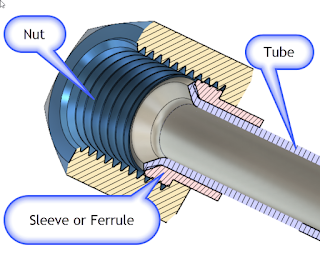
The flare is backed by a sleeve or "ferrule". This reinforces the flare. This design also greatly reduces the possibility of "wiping" damage to the flare, since the nut doesn't turn against the flare itself.
So that's why the design is made the way it is!
The Part in Fusion 360
The part isn't complex, it's just a path created using a couple of 2D sweeps.
The flares at the ends of the parts are revolutions. Just like the paths creating the sweep, there's nothing earth shattering if you're familiar with the tools
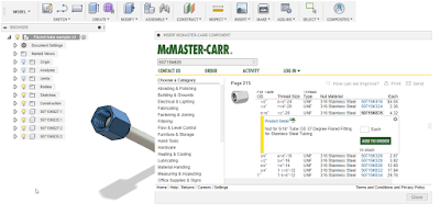
One thing worth noting, I downloaded the flares and sleeves from McMaster Carr, using the tools built right into Fusion 360. That's a nice feature that simplifies downloading and inserting standard parts.
 |
| Inserting from McMaster Carr |
I wrote about that tip here in a post a little ways back. You can check out that post here.
And by the way, here's a link to the part. Feel free to download it and take a look at it!
A Few Other Notes
- McMaster-Carr actually didn't have the fitting I needed. I wanted the fitting in aluminum, which does exist. So I used a steel part and changed the material. Yes. In this case, I'd probably have to go elsewhere to purchase the part. In my case, Aircraft Spruce. Sorry McMaster, I love you, but you didn't have what I needed in this case.
- The parts from McMaster weren't modeled quite right. There's some interference with the threads and the ferrule, and the flare on the ferrule is actually 30 degrees, not 37 degrees. But how much does it matter? If the purchased parts are correct (which they should be), then the fact that the models are slightly incorrect won't make much difference. But it is noticeable in the cross section.
- Aircraft tubing is sized using a unique numbering system. The tubing (and hardware) are assigned a number, such as 3, 4, 5, etc. If you take this number and divide it by "16", you'll get the outside diameter of the tubing in inches. So #3 tube is 3/16, #4 tubing is 4/16, or a 1/4 inch, and so on. The hardware is often number the same way.
- Aircraft tubing is also flared to 37 degrees, not 45 degrees as may be found in other applications. Just in case anyone is wondering why I'm using that flare!
- If you're interested in learning more about flaring, here's a nice video that shows the process of flaring the tubes. It's worth a few minutes of your day!
In Conclusion
I started this project out as a bit of practice, as I said, it was an elaborate doodle. But I had the chance to try a few tricks, and I thought I'd share them with you.
So go ahead and download the part, and have a little fun with it!
Sources and Acknowledgements
Flare Dimensions are from HylockUSA. They also have the dimensions for metric flares!
Part Models are downloaded from McMaster Carr.

No comments:
Post a Comment