Find us on Google+ Inventor Tales

Sunday, June 30, 2013

Conditional Feature Suppression in Autodesk Inventor - Turning a Feature On & Off Automatically

“Some have courage in pleasures, and some in pains: some in desires, and some in fears, and some are cowards under the same conditions.”
Socrates

Sometimes the challenge I encounter isn't knowing which tool in Autodesk Inventor to use, but which tool is best for a given situation.

For example.  Not that long ago, a challenge arose.  I had a part that was going to change size. 

When the size of the part changed, there was text that also needed to change to reflect the changing dimension of the part. 

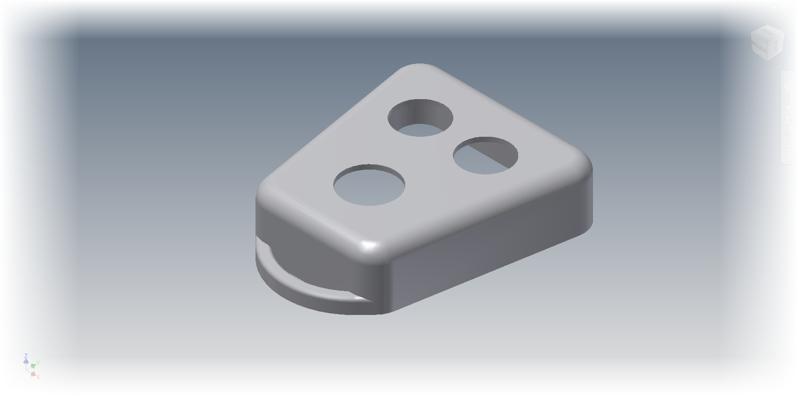
Here I have an example I've created for this blog.  It's of a common wood working tool called a bench dog.

It's a pin, often (but not always) with a square head.  It slides into holes in the workbench and clamps boards from the side for working. 


Bench dog image courtesy Wikipedia


The head has dimensions of 1 inch square, and 1.5 inches square.  I've created text that will identify the bench dog.

The 1 inch bench dog
The 2 inch bench dog.  Different text, with a larger height is used.


Both the height of the text was going to change, and the text itself was going to change. 

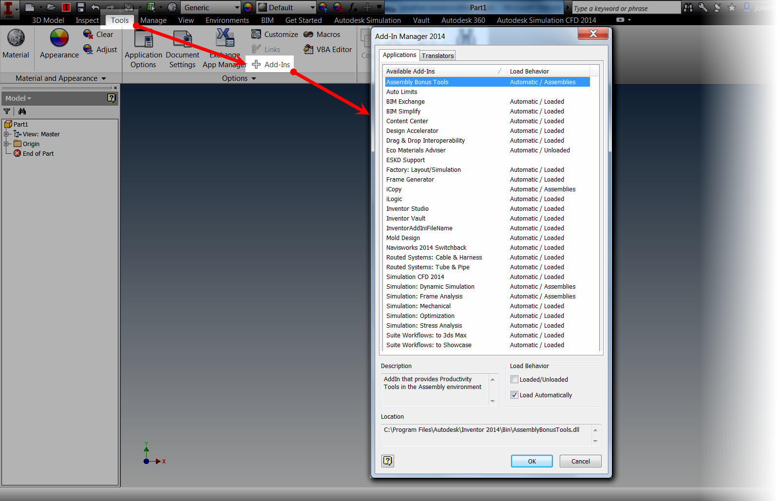
I'm not savvy enough to get into the API and alter it using VBA.   But after reading Bob Van der Donck's blog here, I found a little inspiration. 

 Why not just create multiple features, and suppress them based on the dimension that was changing.  

Below is an example.  Notice that the 1 inch text is suppressed.  It only shows red on the part because I've selected it, and it's previewing for me. 

The "1 inch Bench Dog" text is suppressed.

For what I was doing, it would work! 

I could always us iLogic to suppress the features in question.  It's a simple enough operation for someone familiar with iLogic

But we wanted to avoid iLogic, so the parts could be kept as simple as possible, and could be reproduced by someone familiar with Inventor, but not necessarily iLogic.

And so the "brain-wracking" began.  How can I make this happen,without iLogic.

Then I had my AHA! moment.  Inventor has a tool called Conditional Feature Suppression

What does Conditional Feature Suppression do?  It suppresses a feature based on a dimension!

It's perfect for my case. 

My first step, was to rename the parameter defining the head size of the bench dog to "Dog_Width".  I also made this parameter a Multi-Value list with the values of 1.0 in and 1.5 in.

Creating the Multi-Value List


Adding the values to create the list.

The Mutli-Value list appears as a pulldown
 With the parameters created, I located the 1.0 inch text in the browser, right clicked, and chose Properties.


Accessing the dialog box for Conditional Feature Suppression
One the Properties dialog box opened, I checked the If check box, selected Dog_Width in the pull-down menu, and set the rule so the feature would suppress if the Parameter was anything other than 1 inch.

The options I've selected for the 1.0 inch text.


Now all I had to do was repeat the same steps for the 1.5 inch text, telling it to suppress if the Dog_Width parameter was not equal to 1.5 inches.


The settings for the 1.5 inch text.


And I'm done!  Editing the parameters and toggling between 1.0 inches and 1.5 inches will both change the size of the bench dog, and suppress and unsuppress the appropriate text!


Selecting the 1 inch face size:

Changing the dog.  Note that I've changed filters to shrink the parameters dialog

Selecting the 1.5 inch face size:
The 1.5 inch face.

So go ahead and take a look at Conditional Feature Suppression.  I know there are many out there who love iLogic, and will say that this could just as easily be accomplished with a few lines in an iLogic rule.


And that's true enough.  I'm not trying to say that iLogic isn't appropriate for this.

But what this gives is an option.  The ability to accomplish the same thing without using iLogic and sticking to tools that may be more familiar to the average user than iLogic.

Hey, there's no reason this couldn't be used in conjunction with other iLogic rules! 

So keep this in your bag of tricks.  It may prove helpful someday! 

And as always, check out the video version of this below!

Thursday, June 27, 2013

Released into the "Wild" Autodesk Fusion 360 is Here!

“Fusion will be the final way out for the future.”
Shen Wenquan

Earlier this week, Autodesk announced Autodesk Fusion 360, a cloud based mechanical design tool.

So what does this exactly mean? 

Instead of a heavy 3D modeller sitting on top of your workstation, now you're operating on the cloud. 

The files are stored in the cloud.  In that ethereal world of 1's and 0's, designs are shared, collaborated upon, and versions are tracked, the whole time the design is being created, or "ideated",to use the popular buzzword

In this respect, it reminds me a bit of how I've been storing documents on Google Drive for years.

There's also a nice dashboard where projects can be managed with the design team of other Fusion 360 users.  Combining a bit of a social media site with data storage for design files.

Files can be accessed where ever you have access to your Autodesk Fusion Account, and since the files are on the cloud, they're also accessible, as well as continuously being backed up. 
No more opening your laptop to realize you forgot to copy a file from the server! 

Just yesterday I signed up for my Fusion 360 account.  I'll shortly start creating simple parts, trying some collaboration, and quite simply, kicking the tires on a new way of approaching design.

Here's my new dashboard.  A clean slate ready to get started

So in many ways, I'm still learning about Fusion 360, and I expect to continue learning.  I'm hacking my way with my virtual machete, bullwhip on my hip and fedora on my head, trying to blaze my own new trail into new territory.

I'll be sure to let you know what I find!


And if you're interested in taking a look at Autodesk Fusion 360 yourself, click here to get started!

For more information on Fusion 360, check out the overview below from the Autodesk Fusion 360 team! 


There is also an interesting interview with Autodesk CEO Carl Bass with Bloomberg, where he discusses the cloud, Fusion 360, and even the U.S. Patent System.


Sunday, June 23, 2013

Changing the View Cube Zoom Behavior in Autodesk Inventor

“it's respectful hearing of one another's point of view and perhaps finding some common ground.
Larry Vanderhoef

When I meet and Autodesk Inventor user, I'm often asked, "Do you know how to change behavior "X", in Inventor?"

Sometimes I know the answer, sometimes I don't know the answer, and sometimes, I just have to give it a go!

Earlier this week, was one of those times. 

The question was "When I click on the View Cube to change a view, Inventor zooms out, do you know how to change that?" 

The Inventor user asking the question had a good reason to ask.  The assemblies she worked on were large in dimension, and when rotating on the view cube, Inventor would zoom out, forcing her to zoom back into the area she was originally working on.


Imaging working on this area in Inventor


Then having it zoom out like this when the View Cube is used

The fact was, I didn't know the answer to this one off hand.  I use my 3DConnexion device for navigation, so I don't mess with my View Cube settings much

But I said, "Let's give it a go!"

Fortunately, the solution isn't that difficult.  It's within easy reach.

The first step, is to right click on the View Cube, and choose "Options".

Right click on the View Cube reveals optoins


This will open the View Cube Options dialog box.  When the dialog box opens, find the "Fit-to-View on view change" options, and uncheck the option.


Unchecking "Fit to View on view change"

Now, when clicking on the View Cube, the zoom factor won't change. 

This means that the amount of zooming goes way down.  Now a few pans will keep the area in view and centered.

Note the images below where I used this new setting.  I've used the View Cube to rotate the view in Inventor, without correcting it using the Pan tool.  Also notice the location of the area in the box.  It stays in view now. 

All it takes is a quick pan to center it, and your back in the 3D Modeling game!

Starting here and clicking on the View Cube

Now brings me to here!
Take a look at this option if you're a big user of the View Cube.  You just might find it's an easier way to work with Inventor.

And if you prefer this tip in video form, take a look below!

Sunday, June 16, 2013

Keeping it Current - Updating Materials in and Autodesk Inventor Part


“To me, a building - if it's beautiful - is the love of one man, he's made it out of his love for space, materials, things like that.”
Martha Graham

Since I work on several projects that may be quite dissimilar to each other, I have found that it's pretty easy for my Autodesk Inventor materials to get out of sync with the external material libraries.

That means, that many times I have to update my outdated or inconsistent material libraries with the current materials in my external libraries. 

So using Inventor 2014, what's the process of checking, and updating the materials from my external libraries?

I'm going to start with a sample part.  This part came from a different project, and was originally created in Inventor Release 5.  So this file has some miles (and migrations) on it!


The part I'm working with in this blog
One result of all of this is that the materials don't quite match the materials currently in my library.  So I want to update them as quickly as possible.

I'm going to open my material library with the icon at the top of the Quick Access toolbar.  I can also find the icon on the Tools tab.


Getting to the Material Library
I can see that there are several materials located in the "Document Materials" section.  These are the materials that are cached locally inside the file, and over time may not be in sync with the external libraries, which are displayed on the lower half of the dialog box.

Document and External Material Libraries


But how can I refresh the new, with the old?  It's a matter of using the Update icon found on the Manage tab, in the Styles and Standards panel.


Preparing to update the libraries


Clicking the Update icon will display the Update Styles dialog box.  Choosing the library that I want to update, in this case the Inventor Material Library, I can see which materials require updating.

A list of materials requiring update.


I can click on each material to individually update, or I can click Yes to All and update everything on the screen.  For this particular file, I'm clicking "Yes to All".  I can then hit OK to update the materials from the external libraries.

The libraries are now updated.  As a matter of fact, even the active material in the file will be updated, as can be seen in the image below!


Now that's left to do is save, and carry on!

For a video version of the above post, check out the link below!


Sunday, June 09, 2013

A What's New in Autodesk Inventor 2014 - Creating Self Intersecting Sweeps.

“The stream of time sweeps away errors, and leaves the truth for the inheritance of humanity”
Georg Brandes

I have some friends visiting in from out of town this week, so because of well spent time with them, this blog post is short, and without video.  I hope that it is still a helpful tip, even though it is quite brief.

In the last few weeks, I've been looking through the what's new topics, and seeing what I like. 

One of the tools that for my part, I think is going to be really helpful is the self intersecting sweep.

A self intersecting sweep is a swept feature where the profile intersects itself.  In earlier versions of Inventor, this sweep would be able to solve.  It would error out and fail.

An example of a sweep that would intersect and fail.

This meant readjusting the profile to make sure it didn't intersect.  And while, at least for my part, this hasn't been time consuming to do in the past, there's no beating not having to adjust the sketch at all.

This is where the new Feature in Autodesk Inventor 2014 helps out.  As a matter of fact, it helps out a lot.  It will allow this self intersecting sketch to calculate, and create itself without erroring out. 

A closeup of a radius that would have caused a failure in previous releases of Inventor.
But now, if I accept and hit "OK", Inventor calculates, and creates this sweep without a problem.  How about that!

Ta Daaaa!

I know that for certain profiles I would use, like router profiles in my woodshop projects, this is going to be a nice feature.  I can make sure that the profile matches the same profile my router bits will give me, without worrying about features that can't be swept because of that.

A view of the entire sweep profile

So think about this feature as you move forward into Inventor 2014.  Think of where it can be used for the type of sweep that router profile, where the result is legitimate, but it might not be easy to create because of the profile intersecting.


Think about it because, in fact, it just got a lot easier!


Tuesday, June 04, 2013

A Guest Video on Depth of Field in Autodesk Showcase 2014

It is not length of life, but depth of life.
Ralph Waldo Emerson

I wish I could say that I had I was the absolute guru in Autodesk Showcase.  I wish I could be, to use the corporate buzzword, "the single point of truth". 

But I'm not, and it would be foolish to presume that I am. There are always things for me to learn and make myself better. 

Fortunately, there are plenty of generous Showcase users out in "the 'Verse" who are willing to share information with the rest of the user community.

For this midweek post, I'm sharing some excellent videos shared by Marion Landry on her YouTube channel

These videos have some excellent tips on using Depth of Field in Autodesk Showcase, particularly with some workflows and tips on using Depth of Field in Ray Tracing and Hardware Rendering.

I also like her tips on using shots to save different depth of field views using both hardware rendering and ray tracing, as well as using them in animations!

Take a look at the videos!  They're a great help!

Showcase Tips & Tricks: Showcase 2014 Depth of Field Part 1 


Showcase Tips & Tricks: Showcase 2014 Depth of Field Part 2


Showcase Tips & Tricks: Showcase 2014 Depth of Field Part 3


Sunday, June 02, 2013

Controlling Orientation of a Placed Component in Autodesk Inventor 2014

Future orientation is combined with a notion and expectation of progress, and nothing is impossible.
Alan Dundes

There are times when a component is placed in Autodesk Inventor, it doesn't take the orientation I want it to. It lays on it's side, back, etc.  Every way but the way I want it. 

Inventor can work with this just fine, but ultimately, I like my components sitting in a "natural" state.

Usually, I'll just unground the component, and assembly it to origin planes.  It took little time, and got what I wanted.

But now, 2014 has added a new option, the ability to reorient a component during placement.

  • Let's start with an assembly, where I'm placing a metal container with the Place Component command.  Notice that the container is laying on it's back.  I want it placed on it's bottom, like it would be hanging on a wall. 
    • It's important to note in the image below, that I'm still looking at the preview.  I haven't placed the component by left clicking yet.

The initial preview of the component placement.
  • Now, with the preview on screen, I right click to see the rotation options.  There are options to rotate around the X, Y, and Z axis in 90 degree increments.

Right clicking to see the rotation options.


  • In this example, I've rotated round the X-Axis once, and Y-Axis three times.  (It's a little like a combo on a game console!)


The corrected orientation

  • Finally, the component can be placed by left clicking or by right clicking and choosing Place Grounded at Origin

Placing at Origin
  • And that's all there is to it!  The component is placed and ground, all in the orientation I want!

The component placed!

And below, here's the video portion of the post!  I hope you find it helpful!

Wednesday, May 29, 2013

Autodesk Vault Ribbon Disappears when Starting a Component in Autodesk Inventor 2014 & a Fix

“You're darn right you're picking up the tab!”
Tony Stewart

A little while ago I ran into an issue with my installation of Autodesk Inventor 2014 that, while not a showstopper, was a little annoying.

Every time I started a new component.  My Vault ribbon would disappear.  That's right, just like Nightcrawler from X-Men, it would Bamf! out of existence.

Image courtesy of Wikipedia

I wasn't doing much work in Inventor 2014 at the time, so I would just unload and reload the addin to temporarily fix the issue. 

Finally, I got off my lazy duff and searched for a real solution. 

And out on the Autodesk Discussion Group.  I found it!

I went a head and moved on.  It quickly began collecting dust in the mental archives. 

But low and behold, a comment on a previous blog brought this back into the light.  So I decided to share it before it slipped into the archives yet again.   

It turns out the solution is pretty simple.   The issue is caused by two instances of the EDM Addin running,


Here's the fix:

1) In Inventor, go to Tools> Addins


Finding the Addin


2) The EDM Addin is a hidden addin.  To display it, right click in the Available Addins window and choose Show Hidden Members.


Show hidden member

3) Now check to see if there are two EDM Addins.  Left clicking on the Available Addins will sort them and make it easier to find them.


Checking to see if there are two addins

4) Now that the two addins are located, find the one with the location mscoree.dll. Then uncheck "Load Automatically".


5)  Close the dialog box by clicking "OK", and all is done.  The next time Inventor opens, the Vault tab should appear just fine!


All is good!

Acknowledgements

While I would love to say that I found this solution on my own, and "stake my intellectual flag" on it.  I did not.  I found it off the Autodesk Discussion Group at the link HERE

Thanks to the users who shared what they have found, their assistance is far reaching indeed!


Sunday, May 26, 2013

A Tour of Constraint Relationships in Autodesk Inventor 2014

“Let's think of new opportunities, not past constraints, as we visualize the future of the state that we call home.”
Kathleen Sebelius

Sitting in my hotel room on a business trip to Dallas, Texas, I found myself taking a look at a new feature in Autodesk Inventor 2014, and thought I would go ahead and create a short post on it.

This new feature is "Show Relationship" in an assembly. 

Activating this feature shows the relationships between constraints in the modeling window, in a graphical format.

For this example, I'll use the Craftsman style coffee table I've used dozens of time before.


The constraint relationship glyphs showing on the Craftsman Style Table


By using a graphical representation, the constraint can be easier to visualize, modify, and delete.

The first step to using the relationship is to show them.  This is located on the Assemble Tab by clicking the Show icon.

The Show Relationships tool


Once the icon is selected, I can choose the components I want to show the relationships for.  In this case, I'm just going to look at the table top.

Glyphs will appear where the constraints between the table top and the lower table it's connected to.

The Constraint Relationship glyphs

Right clicking on the constraint glyphs provides the operations that can be performed on this constraint, such as, Edit, Delete, and Suppress, among more.

Right clicking on a glyph will show the editing tools


If the component is moved using the Free Move command, "bands" appear that connect the constraint to its mating components while the command is active.  After this I can right click and choose "OK" to complete the move.

Using the Free Move command to separate components


Clicking on the constraint will also highlight the geometry that the constraint is attached to, giving a quick graphical way of seeing how the constraint is being used to constrain the geometry.  Just like before, right clicking on a constraint will show the options for that constraint

The components move apart, showing the right click options

Updating the assembly will update the constraints and return the component to its original position.


Updating the assembly will restore the constraints

But before I say "take this tool for a spin", there is on other place this tool can help out.

If there are "sick" constraints, such as conflicting constraints, can be graphically diagnosed using the Show Sick Relationships tool.


Showing Sick Constraint Relationship for diagnostic purposes.

With this ability, the Show tool can be used for editing, and for diagnostics!

So on that note, take this tool for a spin!  And in addition, here's a video on the subject!


Sunday, May 19, 2013

Updating to a New Release of Autodesk Inventor - Refresh from Content Center

“You do not destroy an idea by killing people; you replace it with a better one.”
Edward Keating

This weekend's blog post, by nature, has to be a short one, and without video.  This weekend I'm between trips out of state, so I've been busily trying to get caught up, and prepare to leave town again.

Much off this consists of unpacking into the washing machine and directly packing it again! 

But in the spirit of "unpacking and cleaning up", here's a little tip that can help in making the Content Center fasteners in Autodesk Inventor's Assemblies are "cleaned up" as they are moved to 2014

I'm going to start with a Craftsman Style coffee table that I've had in my archives for several years now.


This table uses No 8 x 1.0 inch wood screw that I placed from content center.


But now, these files are old, created from a 2013 library, and not a 2014 library.  So what's one way to make sure that those files are made current.

1) If Autodesk Vault is being used, make sure to check out all the files from Vault.


2) One the Manage Tab, choose the "Refresh Standard Content" Icon.


3) Inventor will display which content is in need of refreshing.  If several different components are being used from Content Center, then multiple components can be selected (or not) in this dialog box.


4) Click the Refresh icon to update the content from the Content Center Libraries.


5) Now all that's left to do is save the assembly, and, if Vault is being used, check the file in.


For some more info on updating the libraries, including migrating custom content libaries from an earlier release of Autodesk Inventor, check out the link on Autodesk Support here!