“(The wins) give us a lot of momentum. We're on top right now, and nothing can bring us down.”
Jamee Juarez
This year, I wasn't able to make it to Autodesk University 2013. Scheduling with class, work, and budget all conspired to keep me away this time.
I was very disappointed that I couldn't attend. There was information I missed, and people I didn't get to see.
Fortunately, the classes are becoming available online, so I can at least get the information, if not raise a glass with my friends and colleagues!
One great class that I that is now offered online is MA2604: Drive Inventor with the Top Down: Alternative Assembly Modeling Techniques by Paul Munford of The CAD Setter Out.
This video is very informative, and well worth watching. I've already added it to my favorites! Take a look at it below:
Be sure to check out the other classes that are available too!

Wednesday, February 05, 2014
Monday, February 03, 2014
Making Use of the OldVersions file in Autodesk Inventor
“Always be a 1st-rate version of yourself instead of a 2nd rate version of someone else.”
One thing that I think is little known about Autodesk Inventor is the OldVersions folder.
For those of us that have used AutoCAD before, it's similar to the *.bak file in AutoCAD. That is, every time a file is saved, a copy of the previous file is saved
In the case of Inventor, the file is placed in a subfolder of the source file's directory. The subfolder is named "OldVersions", and the filename is Filname.XXXX.ipt, for example.
The OldVersions folder creates backups of all Inventor file types, and it's done every time the user hits the save button.
The XXXX part of the name is an number that increments up, starting from 0001. By default, it only saves back one version. Older versions are deleted (more on changing that later).
But what if the time comes to restore an old version of the file? Maybe I've made a huge mistake, and it's easier to grab that old versions file than try to undo everything. Or maybe, a file got corrupted and this may give a better shot at saving it?
How do I employ that file from the OldVersions folder?
I just open the file, and let Inventor take care of the rest.
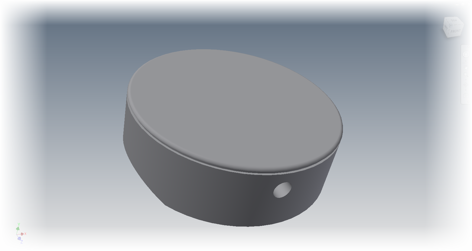
Below is an example of a piston I created. Let's imagine I've made a mistake, and the mistake is so dire, that it's easier to grab that old versions file than edit all the features.
I have an old version in my OldVersions folder, all I have to do is open it.
When I open the file, a dialog box will appear asking what I want to do with the file. In this case, I want to make the Old Version the Current Version.
Choosing OK opens the file, and it will now become the current version. I can now start using the file from that point in time.
There's one other thing that's worth noting. The number of OldVersions kept can be changed inside the project file.
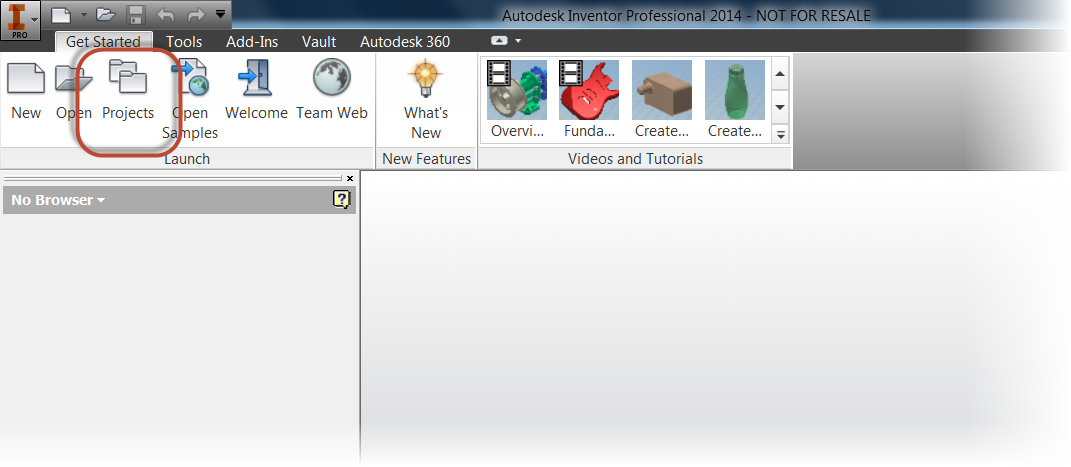
First edit the project file from the getting started tab.
Once in the Project Editor, locate the project in use. In the Options section, there's a setting for Old Versions to Keep on Save.
Right Click to edit it, and it can be changed to any number I want! If I change it to -1, it will keep all versions of the file. It will never purge a single one!
So that's a tip on using old versions! I hope you never need it, but it's a good resource to have if you do.
And for more, here's a video!
One thing that I think is little known about Autodesk Inventor is the OldVersions folder.
For those of us that have used AutoCAD before, it's similar to the *.bak file in AutoCAD. That is, every time a file is saved, a copy of the previous file is saved
In the case of Inventor, the file is placed in a subfolder of the source file's directory. The subfolder is named "OldVersions", and the filename is Filname.XXXX.ipt, for example.
The OldVersions folder creates backups of all Inventor file types, and it's done every time the user hits the save button.
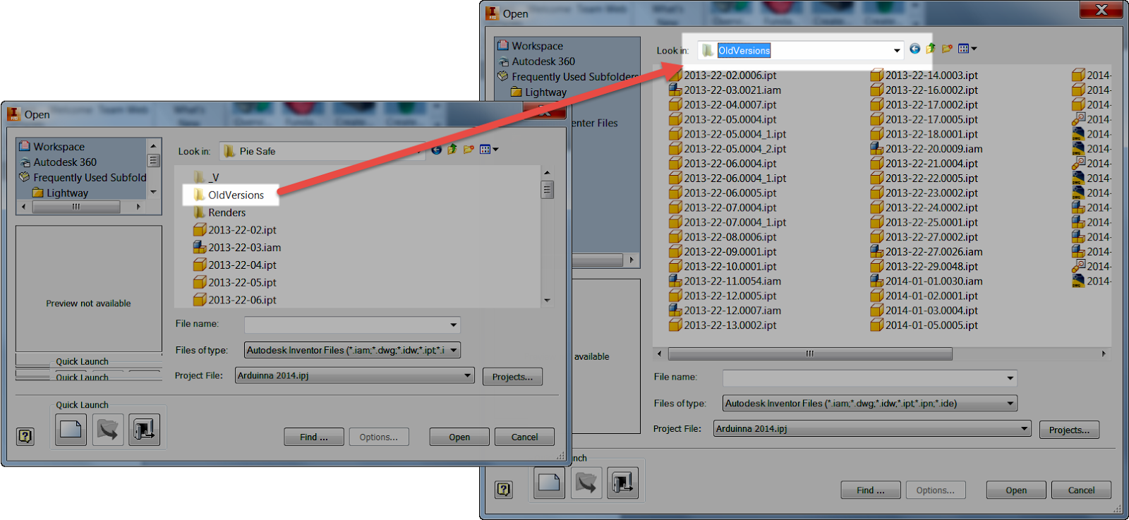 |
| Example of the OldVersions Folder |
The XXXX part of the name is an number that increments up, starting from 0001. By default, it only saves back one version. Older versions are deleted (more on changing that later).
But what if the time comes to restore an old version of the file? Maybe I've made a huge mistake, and it's easier to grab that old versions file than try to undo everything. Or maybe, a file got corrupted and this may give a better shot at saving it?
How do I employ that file from the OldVersions folder?
I just open the file, and let Inventor take care of the rest.
Below is an example of a piston I created. Let's imagine I've made a mistake, and the mistake is so dire, that it's easier to grab that old versions file than edit all the features.
I have an old version in my OldVersions folder, all I have to do is open it.
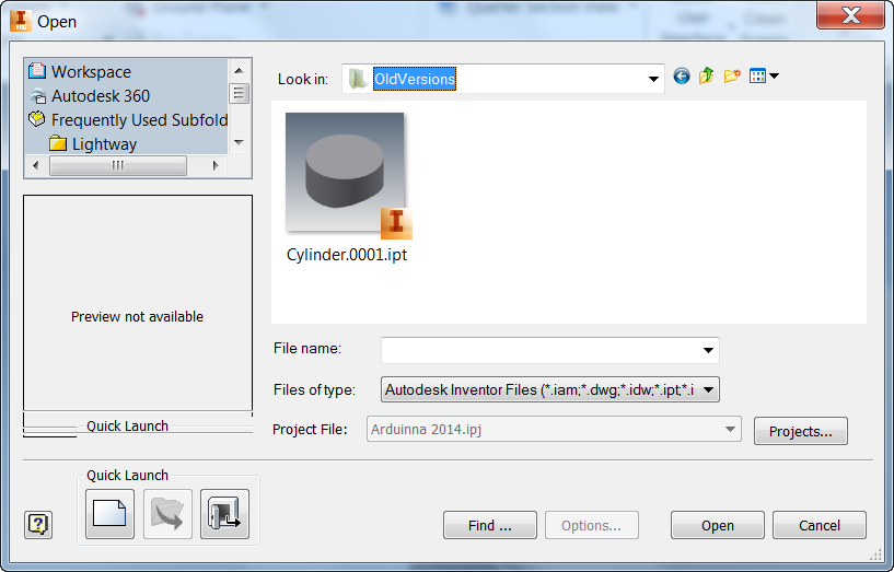 |
| The previous version of the file, in the OldVersions Folder |
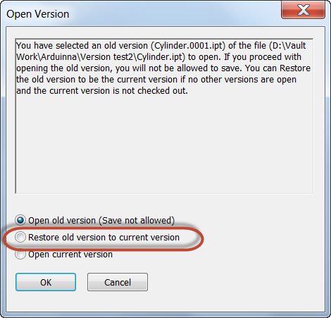 |
| Restoring the old version |
 |
| The old version restored! |
First edit the project file from the getting started tab.
Once in the Project Editor, locate the project in use. In the Options section, there's a setting for Old Versions to Keep on Save.
Right Click to edit it, and it can be changed to any number I want! If I change it to -1, it will keep all versions of the file. It will never purge a single one!
So that's a tip on using old versions! I hope you never need it, but it's a good resource to have if you do.
And for more, here's a video!
Thursday, January 30, 2014
Autodesk Remote..... How it Saved Bacon.... Where Bacon = Time
“Extraordinary creature! So close a friend, and yet so remote.”
Thomas Mann
My Dad had a saying.... "That really saved our bacon." I heard him say it countless times.
Earlier this week, I had reason to heard that quote echo in my ears.
I was faced with a big challenge. I needed to install Autodesk Vault Professional on a computer in our training room, restore a filestore and database, perform some testing, and upload the data when it was all done.
And while one of the training machines was an ideal place to do this, the problem was that there was a class using that training room for three days!
Three days! So what to do? I didn't want to lose three days waiting for the room to free up! And staying late?!? No way!
So, I turned to a solution from the Autodesk Exchange: Autodesk Remote. Important note! You have to be on subscription to use it!
So what exactly is Autodesk Remote?
From the Autodesk Exchange Website...
Autodesk® Remote is a stand-alone application for Microsoft Window 7 and 8 and is compatible with all Autodesk products. It lets you drive Autodesk software installed on your primary computer from a remote computer for fast access to native design data over standard networks. To use it, simply install Autodesk Remote on the PC you want to share. Install it again on the machine you want to connect from and start your connection. Note: dual monitor support is the #1 request from early adopters. We’re listening and actively working on it for the next release.
In short, it lets you run one computer from another via your Autodesk ID. Then you drive one computer, from another.
I can hear everyone now "That's just like (insert name of app)". And you're probably right. There are a ton of tools both free, and not free, that will do exactly what Autodesk Remote did.
And if you're happy with your app... Use it! I'm not writing this to create a mass exodus from your app off choice.
So why am I writing a post about this one?
Because it filled a niche, when I needed it. It was the perfect tool at the right time, for exactly the situation I was facing.
So what did Autodesk Remote do that was worthy of heavenly lights and voices singing?
First, what problems was I facing?
I had to...
Autodesk Remote saved me by...
So if you do work remotely with computers in your network on a regular basis. Take a look Autodesk Remote. The bacon you save might be your own...
It's also important to note that Autodesk Remote that let you remote to your computer from an iPad as well. However, I didn't use it with my iPad. Just my laptop.
If anyone has use the iPad app, feel free to share a comment!
Thomas Mann
My Dad had a saying.... "That really saved our bacon." I heard him say it countless times.
Earlier this week, I had reason to heard that quote echo in my ears.
I was faced with a big challenge. I needed to install Autodesk Vault Professional on a computer in our training room, restore a filestore and database, perform some testing, and upload the data when it was all done.
And while one of the training machines was an ideal place to do this, the problem was that there was a class using that training room for three days!
Three days! So what to do? I didn't want to lose three days waiting for the room to free up! And staying late?!? No way!
So, I turned to a solution from the Autodesk Exchange: Autodesk Remote. Important note! You have to be on subscription to use it!
So what exactly is Autodesk Remote?
From the Autodesk Exchange Website...
Autodesk® Remote is a stand-alone application for Microsoft Window 7 and 8 and is compatible with all Autodesk products. It lets you drive Autodesk software installed on your primary computer from a remote computer for fast access to native design data over standard networks. To use it, simply install Autodesk Remote on the PC you want to share. Install it again on the machine you want to connect from and start your connection. Note: dual monitor support is the #1 request from early adopters. We’re listening and actively working on it for the next release.
In short, it lets you run one computer from another via your Autodesk ID. Then you drive one computer, from another.
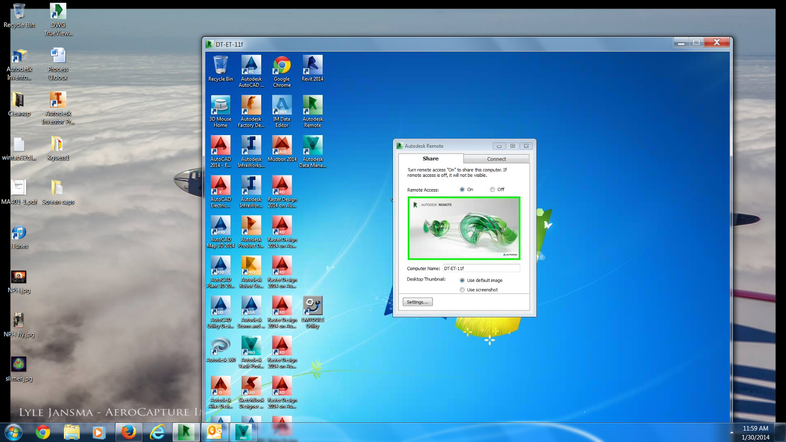 |
| Remoting to one machine from another |
And if you're happy with your app... Use it! I'm not writing this to create a mass exodus from your app off choice.
So why am I writing a post about this one?
Because it filled a niche, when I needed it. It was the perfect tool at the right time, for exactly the situation I was facing.
So what did Autodesk Remote do that was worthy of heavenly lights and voices singing?
First, what problems was I facing?
I had to...
- install Vault Professional 2014
- configure a license file to run Vault Professional 2014
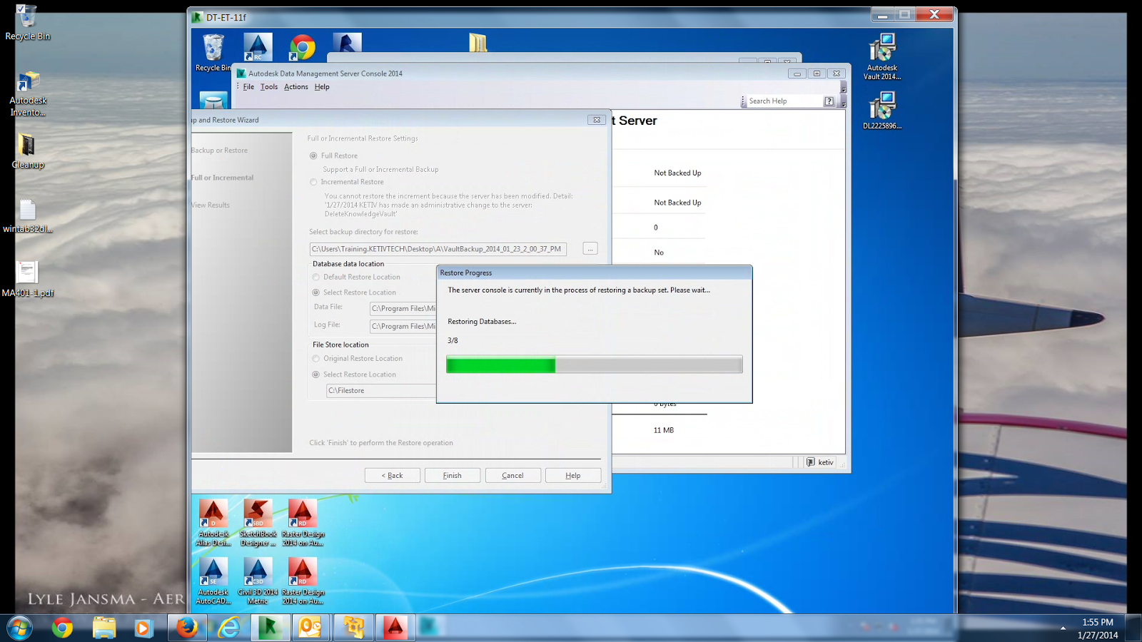
- restore a backup to Vault
- test data once Vault was configured
- upload data to an FTP site once the tests were over
- I had to do all of this without being able to access the machine I was using as a server
Autodesk Remote saved me by...
- installing quickly. Class started at 8:30am. I installed around 8:20am, and was done in less than 5 minutes
- Connection was fast. I had no problems connecting. It took me more time to walk back to my desk than to make the connection
- allowing me to completely run steps 2 and 3 from my desk, in another room
- because I was able to accomplish tests 2 and 3, steps 4, 5, and 6 were done at least a full day than if I had to touch the computer
So if you do work remotely with computers in your network on a regular basis. Take a look Autodesk Remote. The bacon you save might be your own...
 |
| Saving time.... saving bacon.... |
It's also important to note that Autodesk Remote that let you remote to your computer from an iPad as well. However, I didn't use it with my iPad. Just my laptop.
If anyone has use the iPad app, feel free to share a comment!
Friday, January 24, 2014
I Forgot to Add Express Tools to AutoCAD! Now What?
“There is a way in which the collective knowledge of mankind expresses itself, for the finite individual, through mere daily living... a way in which life itself is sheer knowing.”
Anonymous
One thing that can easily happen when installing any version or flavor of AutoCAD is to forget to install the Express Tools.
It's easy to miss them, but if they need to be added after installation, it's not hard at all.
Here's the steps to do it!
The first thing to do, is locate Add/Remove Programs in the Windows Control Panel. Find AutoCAD, and right click on it. Choosing Uninstall/Change.
I'm using AutoCAD Mechanical 2014. Keep in mind you may have a different version or flavor of AutoCAD!
AutoCAD's installer will start. Choose Add or Remove Features on the first screen that appears.
Click through the screens until a list of AutoCAD Features appears. If Express tools has a red 'X' on it, check the box so it has a green arrow like in the image below. Once Express Tools is selected, click Update.
AutoCAD will update. Let it run, finishing when it completes.
Once the update is complete close the installation dialogs and start AutoCAD.
If the Express Tools don't load, there may be one more step that has to be done.
Type CUILOAD at the AutoCAD command line. Choose browse and locate the file acetmain.cuix. The default location in Windows 7 is:
C:\Users\<username
>\AppData\Roaming\Autodesk\AutoCAD Mechanical 2014\R19.1\enu\Support\acetmain.cuix.
But bear in mind that the location can vary slightly with different versions of AutoCAD, and system configurations.
Click Open to close the first dialog box.

Choose , followed by Close to load the *.cuix file and then close to dismiss it.
After these steps are done, the Express tab should appear in your AutoCAD installation, and you're ready to go!
And for a video showing the above procedures, take a look below!
****************Edit 31-October-2014 HAPPY HALLOWEEN! ************************
Just yesterday, I used this very technique to add Express Tools to a users machine. And while all the toolbars were added successfully, I received a "Unknown Command" warning when trying to execute one of the Express Tools functions.
Fortunately a quick Google search found the following result on the Autodesk Website
The steps I used was to type OPTIONS, and on the files tab, choose the Browse button.
Navigate to the following directory\Program Files\Autodesk\AutoCAD 20XX\Express , and choose the Add button to add the path to the support directory.
Once I had done that, the Express tools were working just fine!
Anonymous
One thing that can easily happen when installing any version or flavor of AutoCAD is to forget to install the Express Tools.
It's easy to miss them, but if they need to be added after installation, it's not hard at all.
Here's the steps to do it!
The first thing to do, is locate Add/Remove Programs in the Windows Control Panel. Find AutoCAD, and right click on it. Choosing Uninstall/Change.
I'm using AutoCAD Mechanical 2014. Keep in mind you may have a different version or flavor of AutoCAD!
 |
| Choose "Uninstall/Change" from the control panel |
AutoCAD's installer will start. Choose Add or Remove Features on the first screen that appears.
 |
| Choose "Add or Remove Features" |
Click through the screens until a list of AutoCAD Features appears. If Express tools has a red 'X' on it, check the box so it has a green arrow like in the image below. Once Express Tools is selected, click Update.
 |
| Make sure to select Express Tools and choose update. |
AutoCAD will update. Let it run, finishing when it completes.
 |
| Updating the feasture |
If the Express Tools don't load, there may be one more step that has to be done.
Type CUILOAD at the AutoCAD command line. Choose browse and locate the file acetmain.cuix. The default location in Windows 7 is:
C:\Users\<
>\AppData\Roaming\Autodesk\AutoCAD Mechanical 2014\R19.1\enu\Support\acetmain.cuix.
But bear in mind that the location can vary slightly with different versions of AutoCAD, and system configurations.
Click Open to close the first dialog box.
Choose , followed by Close to load the *.cuix file and then close to dismiss it.
 |
| Loading and closing the menu |
After these steps are done, the Express tab should appear in your AutoCAD installation, and you're ready to go!
 |
| Ta Da! There it is! |
****************Edit 31-October-2014 HAPPY HALLOWEEN! ************************
Just yesterday, I used this very technique to add Express Tools to a users machine. And while all the toolbars were added successfully, I received a "Unknown Command" warning when trying to execute one of the Express Tools functions.
Fortunately a quick Google search found the following result on the Autodesk Website
The steps I used was to type OPTIONS, and on the files tab, choose the Browse button.
 |
| Browse to the path |
Navigate to the following directory
 |
| The path added in |
Once I had done that, the Express tools were working just fine!
Monday, January 20, 2014
Using Raster Views in an Autodesk Inventor Drawing
“There's no sense in being precise when you don't even know what you're talking about.”
John von Neumann
One of the new functions in Autodesk Inventor 2014 is creating a drawing view as a raster view, and allowing the user to make it precise at the time of their choosing.
For starters, what's the point of starting a view as a raster image, then making it precise later.
Simply put, it lets the user to defer the full calculation of drawing views until later. Imagine this on a large drawing view with a lot of calculations involved. Now extend that across multiple projected views. It can take quite a while!
Placing the views as raster views lets the user quickly place the views initially, then choose which views to make precise when needed. The "hit" on calculation can be spread out over time. Make one view precise, and work on it? Going to a meeting? Calculate another view while you're gone! Going to lunch? Make another view precise, and so on!
So that's the purpose of it! Now, how does it work.
When creating a base view on a drawing sheet, there's a check box to Raster Views Only. With this check box selected, the views will be placed quickly.
Aside from selecting that check box, placing views is the same. Once the views are placed, there will be green brackets around the views that are being represented as raster views.
At some point, however, it will become necessary to make the views precise. To do that, right click on the view, and choose Make View Precise.
The green brackets will disappear, and the view is now precise.
Other views can be made precise later, when they're needed. The views don't have to be calculated at once!
And for a video description of the steps! Take a look below!
And for even more information on this tool, take a look at the Autodesk Online help video at the link here!
John von Neumann
One of the new functions in Autodesk Inventor 2014 is creating a drawing view as a raster view, and allowing the user to make it precise at the time of their choosing.
For starters, what's the point of starting a view as a raster image, then making it precise later.
Simply put, it lets the user to defer the full calculation of drawing views until later. Imagine this on a large drawing view with a lot of calculations involved. Now extend that across multiple projected views. It can take quite a while!
Placing the views as raster views lets the user quickly place the views initially, then choose which views to make precise when needed. The "hit" on calculation can be spread out over time. Make one view precise, and work on it? Going to a meeting? Calculate another view while you're gone! Going to lunch? Make another view precise, and so on!
So that's the purpose of it! Now, how does it work.
When creating a base view on a drawing sheet, there's a check box to Raster Views Only. With this check box selected, the views will be placed quickly.
 |
| Checking the Raster Views Only checkbox |
Aside from selecting that check box, placing views is the same. Once the views are placed, there will be green brackets around the views that are being represented as raster views.
 |
| Green brackets indicate these are raster views |
 |
| Calculating the views into precise views. |
The green brackets will disappear, and the view is now precise.
 |
| One view is precise now. The others can be calculated later, when needed. |
And for a video description of the steps! Take a look below!
And for even more information on this tool, take a look at the Autodesk Online help video at the link here!
Wednesday, January 15, 2014
Controlling Component Participation in an Assembly Level Feature in Autodesk Inventor
As an artist, I've always wanted to participate in the dialogue of art with other artists.
Jeff Koons
I've always considered assembly level features a bit of a specialty tool in Autodesk Inventor. That doesn't mean I don't think it's a valuable tool. It just means that it seems like there are users who really use it, and there are users who never touch it, with very little middle ground.
When I'm playing around with wood working projects, I use it a lot. It's perfect for creating things like dowel holes and hinge slots. These features are typically creating in components that are already assembled together in wood working.
Today, I was slowly building a Pie Safe in Inventor from plans I found in a Fine Woodworking article, and the time came to add the hinges to the doors.
The hinges need to have clearance cut for them, which is pretty common, even expected.
Since the door would be assembled by this point in the construction, I reached for my assembly feature, created my sketch, and extruded my cut.
And something happened I had forgotten about. Inventor cut the slot alright! But it cut right through the hinge too! The assembly feature cut everything in it's way!
At first glance, one might think that this tool isn't very helpful if it's going to blindly cut everything that gets in it's way. But Inventor does give us the ability to control what the assembly feature cuts. All that's needed are a couple of clicks.
The first thing I need to do, is locate the assembly feature in the browser. Expand it, and a list of the components that are "participating" in the extrusion appear. In this case, it's the component making up the edge of the door (2013-22-27:3) and the two hinge leaves (Generic Hinge1:1 & Generic Hinge2:1).
What I really need to do is tell Inventor not to have the hinge leaves participate in the extrusion!
I do that by selecting each hinge leaf, and choosing "Remove Participant".
Once the hinge leaves are removed from the feature. Everything looks as it should! My design intent is truly captured!

So that's how to tell Inventor not to include components in an assembly level cut. If you're using this tool, I think this could be an important aspect that could get easily overlooked.
And as one last tip, what if a component needs to be added to the assembly level feature, that is told that it needs to participate?
If that's the case, right click on the feature, choose "Add Participant" and select the components you wish to add. Give it a try!
And for a video on the steps I showed above, take a look below!
And one final note, more information on the assembly level feature can be found in the Inventor help system here!
Jeff Koons
I've always considered assembly level features a bit of a specialty tool in Autodesk Inventor. That doesn't mean I don't think it's a valuable tool. It just means that it seems like there are users who really use it, and there are users who never touch it, with very little middle ground.
When I'm playing around with wood working projects, I use it a lot. It's perfect for creating things like dowel holes and hinge slots. These features are typically creating in components that are already assembled together in wood working.
Today, I was slowly building a Pie Safe in Inventor from plans I found in a Fine Woodworking article, and the time came to add the hinges to the doors.
 |
| A 'Quickndirty' rendering I created in Autodesk Showcase |
The hinges need to have clearance cut for them, which is pretty common, even expected.
 |
| A typical hinge pocket. Image courtesy Fine Homebuilding |
And something happened I had forgotten about. Inventor cut the slot alright! But it cut right through the hinge too! The assembly feature cut everything in it's way!
 |
| Doh! That's not what I wanted! |
At first glance, one might think that this tool isn't very helpful if it's going to blindly cut everything that gets in it's way. But Inventor does give us the ability to control what the assembly feature cuts. All that's needed are a couple of clicks.
The first thing I need to do, is locate the assembly feature in the browser. Expand it, and a list of the components that are "participating" in the extrusion appear. In this case, it's the component making up the edge of the door (2013-22-27:3) and the two hinge leaves (Generic Hinge1:1 & Generic Hinge2:1).
 |
| Components participating in the feature |
I do that by selecting each hinge leaf, and choosing "Remove Participant".
 |
| Removing the participants |
Once the hinge leaves are removed from the feature. Everything looks as it should! My design intent is truly captured!

So that's how to tell Inventor not to include components in an assembly level cut. If you're using this tool, I think this could be an important aspect that could get easily overlooked.
And as one last tip, what if a component needs to be added to the assembly level feature, that is told that it needs to participate?
If that's the case, right click on the feature, choose "Add Participant" and select the components you wish to add. Give it a try!
 |
| Participants can also be added to an assembly level feature |
And for a video on the steps I showed above, take a look below!
And one final note, more information on the assembly level feature can be found in the Inventor help system here!
Monday, January 13, 2014
A Review - A Look at Infinite Skills "Learning Autodesk Inventor 2014"
Back near the end of 2013, I was asked to review Learning Autodesk Inventor 2014 video based training created by Infinite Skills. So I took some time, dove deep. I wanted to not just take an overview. I wanted to dig into it and really understand it.
Before starting anything, I think it's important I say that I didn't get compensated in any way for this. I was just given a link to download the files, and then the freedom to take a look at the files. Beyond being supplied training files, I was free to formulate my own opinions.
With that out of the way, I'd like to start out with how I see video training. Personally, I'm a big fan of video based training. I've created several videos myself, and I use them whenever possible.
However, having instructed several courses myself, I've always thought that they couldn't replace class based training. I've just thought it's too hard to replace the interaction, and experience of live instructor. I guess you can say I'm a little biased that way.
But it's time to set my biases aside and take a good look.
What I liked!
The first thing I did, was take some time to get used to navigating the viewer. I found that it's easy to get used to and simple to use. There was also a pretty good help system if I had a question on the navigation.
The videos are organized into fairly short segments, most of them a few minutes long. I thought this made it easy to take them in small increments and avoid getting overwhelmed.
 |
| And example of the videos organized |
 |
| An example of the lessons on screen. |
I also noticed that he pointed out things that he did out of his preference. Not because it was a "better" way to use Inventor. Just that he liked a setting, or this approach, and why he does it. It shows his experience, and an understanding that there are many approaches that work, and each user can choose which they like at their discretion.
I also quickly noticed was the depth of information that was included in the videos. Far more information that I felt I could give in a lecture. That level of information would be too overwhelming in a lecture format.
 |
| An example of depth of information. Talking about Application Options |
The nature of having the lessons in a video format, with the ability to bookmark them, made for a much easier mechanism to take in the information being provided.
Which brings me to what I found to be another useful feature. The bookmarks. At any point a video can be bookmarked so it can be returned to at a later time. So if a subject of particular interest is found, it can be bookmarked, complete with a title and description, for later reference.
 |
| The bookmark page. VERY useful! |
What I didn't like so much
While my overall impressions were very good, nothing is perfect. And while I won't say there's something "bad", there are some things that I wish were better.
To begin, as much as I liked the amount of information being, I think there's a chance the information could become "drinking from a fire hydrant" for the new user. I would certainly recommend reviewing the videos and using the bookmarks to their full advantage
And this one is a pet peeve of mine, pure and simple. Every once in a while, the key strokes came through on the video. While the information is all good, and it in no way impacts the quality of the information, I would have been a happier not hearing them. Granted, I was using a headset with the videos, which makes the keystrokes more prominent. Yes. It's a minor thing. But as I said, a peeve of mine.
My conclusion?
I like the Infinite Skills Inventor 2014 videos. I think they're an excellent learning resource for someone looking for some self paced learning, at home, or on the job. The videos are well structured and have all the information needed to provide someone a solid foundation using Autodesk Inventor.
The amount of information provided is very thorough. I like that. I like the ability to see the different settings and approaches for tools in Inventor. Being someone who likes to see the options and choose one I like the best, I like the depth of information that was provided.
At the price point of $99.95 USD, the investment isn't going to "break the bank", especially when compared to the time lost and frustration of the "hunting and pecking" method of learning software. Money spent on good training will save time when the software is used "in the wild".
My ultimate conclusion? I think this is an outstanding learning resource!
Wednesday, January 08, 2014
Making the Right Selection - Selection Tricks in Autodesk Showcase
Design is not making beauty, beauty emerges from selection, affinities, integration, love.
Louis Kahn
Once again Marion Landry has come through with a great post on selecting objects in Autodesk Showcase.
While selecting objects in Showcase isn't a difficult task, there are always tricks that will make it even easier.
Check out some of Marion's tricks that make selecting objects Showcase a snap!
Friday, January 03, 2014
WHAT DID I JUST DELETE?!? - Recovering a Deleted File from Dropbox
I am prepared for the worst, but hope for the best.
Benjamin Disraeli
Over a year ago, I created a "poor man's" Autodesk Vault backup scheme using my Dropbox account.
In short, my Vault Data is backed up to a folder that syncs to my Dropbox account, creating a simple cloud backup.
Information on how I did that are found in my post here.
I've been using it for a year, and it's worked great. I've never had a problem with it.
That is until now....
First, this wasn't a problem with the scripts, my internet connection, or Dropbox.
Each one of these tools worked flawlessly.
It was the user (that's me!) who screwed this up!
So what did the user do?
I had to restore a different Vault Database and Filestore for a customer test. I ran the backup, which actually failed because I didn't have enough disk space.
But that, is a separate issue.
The rub? I neglected to make sure I had a safe backup of my own Vault data in a safe place.
So what happened?
My scripts ran just like they were set to. They removed the data from my dropbox folder, in order to make it ready to be replaced by a new backup....
Which was never made due to the failed backup of customer data...
And my cloud Vault backup was destroyed.
Had I really just effectively killed all my personal Vault data?
Thankfully, no. Lucky for me, Dropbox has a way to restore lost data.
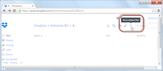
First, browse to the folder where the data was, and choose "Show Deleted Files"
A list of the deleted files will be displayed. Now right click on the files to be restored, and choose "Restore"!

Now the files are resurrected, and all is good again!
Needless to say, that backup is now residing in a safe, safe place!
For the full instructions on recovering a file deleted from Dropbox, check out their help at the link HERE! There's more than one way to do it!
Benjamin Disraeli
Over a year ago, I created a "poor man's" Autodesk Vault backup scheme using my Dropbox account.
In short, my Vault Data is backed up to a folder that syncs to my Dropbox account, creating a simple cloud backup.
Information on how I did that are found in my post here.
I've been using it for a year, and it's worked great. I've never had a problem with it.
That is until now....
First, this wasn't a problem with the scripts, my internet connection, or Dropbox.
Each one of these tools worked flawlessly.
It was the user (that's me!) who screwed this up!
So what did the user do?
I had to restore a different Vault Database and Filestore for a customer test. I ran the backup, which actually failed because I didn't have enough disk space.
But that, is a separate issue.
The rub? I neglected to make sure I had a safe backup of my own Vault data in a safe place.
So what happened?
My scripts ran just like they were set to. They removed the data from my dropbox folder, in order to make it ready to be replaced by a new backup....
Which was never made due to the failed backup of customer data...
And my cloud Vault backup was destroyed.
Had I really just effectively killed all my personal Vault data?
Thankfully, no. Lucky for me, Dropbox has a way to restore lost data.
First, browse to the folder where the data was, and choose "Show Deleted Files"

A list of the deleted files will be displayed. Now right click on the files to be restored, and choose "Restore"!

Now the files are resurrected, and all is good again!
Needless to say, that backup is now residing in a safe, safe place!
For the full instructions on recovering a file deleted from Dropbox, check out their help at the link HERE! There's more than one way to do it!
Tuesday, December 24, 2013
How Do You Look at it? - Look at plane on Sketch Creating in Autodesk Inventor
A man should look for what is, and not for what he thinks should be.
Albert Einstein
When I train an Autodesk Inventor class, I make a point to try to tell my students what settings I change solely for the purpose of my own preference. There's no reason to change that setting if they prefer a different setting.
Everyone has different preferences, and everyone should be allowed to choose for themselves.
I'll often speak of "settings Jon changes on every new install of Inventor".
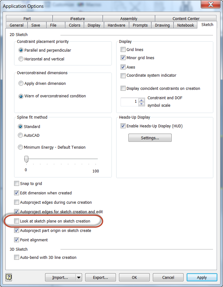
And one of them is "Look at Sketch Plane on Sketch Creation". It's found by choosing Tools>Application Options and finding the Sketch Tab By default it's turned on in Inventor. I turn it off right away.
First of all, what does it do? When checked, Inventor will automatically turn the view to look perpendicular to a sketch plane when a sketch is created.
Before creating the sketch, I have the view rotated in an Isometric view
After creating the sketch the view is rotated so the view is perpendicular to the sketch.
I know that there are many who like this setting. However, personally, I'm not a fan. I always found I was rotating the view back most of the time. So what to I do?
I turn it off! Just like I have below.
Now, Inventor won't turn the view for me. While this means I may have to turn the view myself, I prefer it because I turn the view when I want to. Which I find much more comfortable for me.
So there it is! A setting that I change, and why I change it, which really just boils down to personal preference.
What do you think? Do you prefer the default behavior? Feel free to drop a comment!
And for the video version of this setting, take a look below!
Albert Einstein
When I train an Autodesk Inventor class, I make a point to try to tell my students what settings I change solely for the purpose of my own preference. There's no reason to change that setting if they prefer a different setting.
Everyone has different preferences, and everyone should be allowed to choose for themselves.
I'll often speak of "settings Jon changes on every new install of Inventor".
And one of them is "Look at Sketch Plane on Sketch Creation". It's found by choosing Tools>Application Options and finding the Sketch Tab By default it's turned on in Inventor. I turn it off right away.
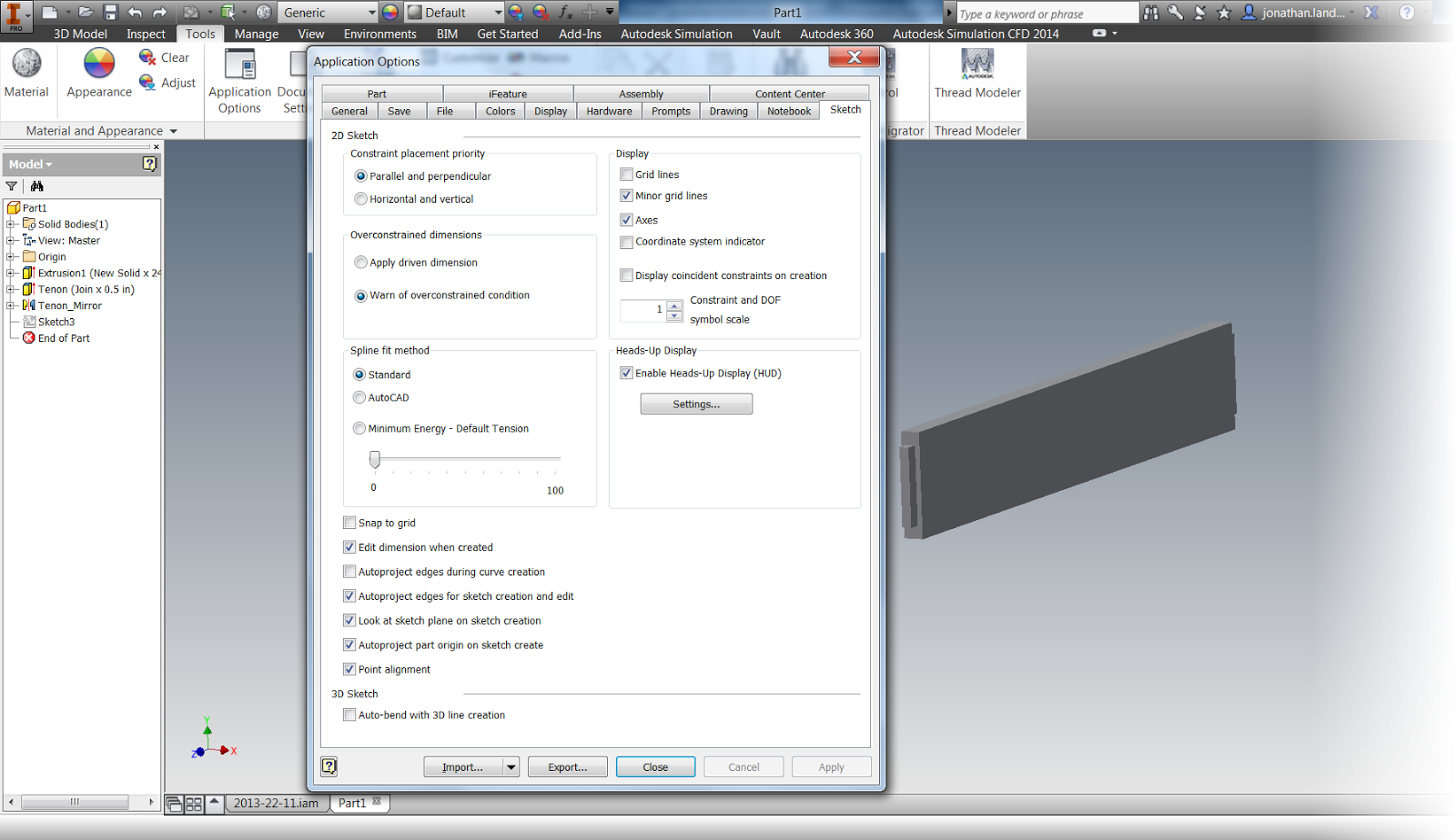 |
| The default settings. |
Before creating the sketch, I have the view rotated in an Isometric view
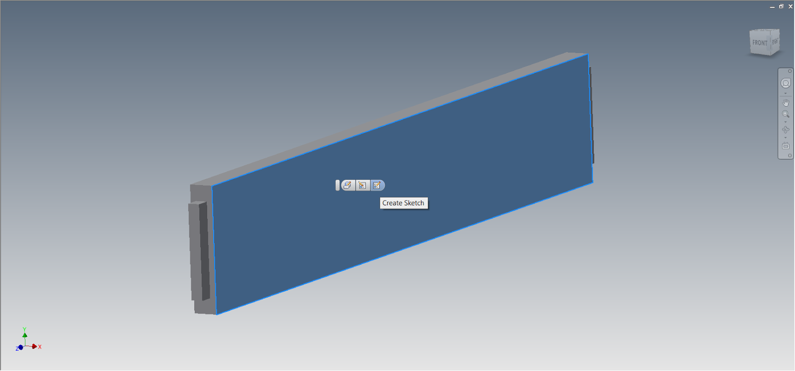 |
| Before creating the sketch |
After creating the sketch the view is rotated so the view is perpendicular to the sketch.
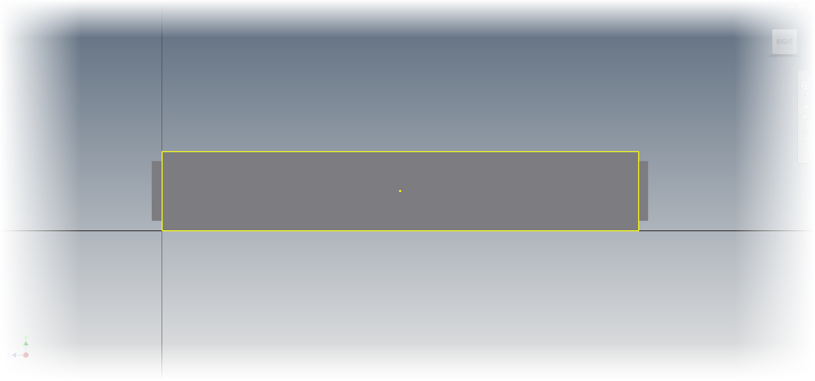 |
| After creating the sketch |
I know that there are many who like this setting. However, personally, I'm not a fan. I always found I was rotating the view back most of the time. So what to I do?
I turn it off! Just like I have below.
 |
| Turning the setting off |
So there it is! A setting that I change, and why I change it, which really just boils down to personal preference.
What do you think? Do you prefer the default behavior? Feel free to drop a comment!
And for the video version of this setting, take a look below!
Thursday, December 19, 2013
That's a Wrap! One Semseter of Powerplant Courses finished!
“We're trying to improve our skills, we're trying to improve our record and we want to have an enjoyable experience.”
Brian Gasser
After 16 weeks of long slogging in my powerplant courses at Mount San Antonio College, this semester is done!
It was a though experience. It was stressful, it was frustrating. It meant missing events with friends.
But it was immensely rewarding.
For the last 15 years or so, I've worked in a computer industry. It's a rewarding career, I love being a part of technology and watching it evolve.
But going into those powerplant courses reminded me of what it takes not only make things work, but keep them working.
What did I do in my class?
With the help of my lab partner, I did the following:
1) Disassebled, inspected and checked a Magneto
2) Timed Magnetos on an aircraft engine
3) Helped troubleshoot a malfunctioning engine
4) Disassembled and reassembled a 4 cylinder engine
5) Used non-destructive testing to check pistons and crankshafts for cracks.
6) Removed fan blades from a JT9 Turbine Engine
Every one of these experiences, not to mention hearing the experiences of my instructors, and even the other students added a whole new facet to my knowledge
In that relatively short amount of time, I'm able to speak to those "in the real world" and better understand what they go through every day, and why they sometimes "curse the designers" who didn't think about fixing equipment.
In all, it made me better than the sum of my parts.
So in summary, will I be back? Yes, I plan on continuing my classes, although I will slow my pace a bit. 16 weeks of class, plus full time work, was a little too much for this brain and body.
I'll skip the intercession for now, and take a lighter load next semester. But back I will be.
There is much more to experience out there, and I'd like to see it!
Brian Gasser
After 16 weeks of long slogging in my powerplant courses at Mount San Antonio College, this semester is done!
It was a though experience. It was stressful, it was frustrating. It meant missing events with friends.
But it was immensely rewarding.
For the last 15 years or so, I've worked in a computer industry. It's a rewarding career, I love being a part of technology and watching it evolve.
But going into those powerplant courses reminded me of what it takes not only make things work, but keep them working.
What did I do in my class?
With the help of my lab partner, I did the following:
1) Disassebled, inspected and checked a Magneto
 |
| Timing a magneto. It takes patience. |
 |
| Timing magnetos to an engine. This also takes time an patience! |
 |
| The engine we had to troubleshoot. It ended up being a loose induction hose. |
4) Disassembled and reassembled a 4 cylinder engine
 |
| Our Lycoming 4 cylindder engine disassembled |
5) Used non-destructive testing to check pistons and crankshafts for cracks.
 |
| Connecting rods in the magnaflux machine |
 | |
| A sample picture of cracks revealed by magnaflux. Image courtesy Riverina Air Motive Repair. |
 |
| That's me! Removing blades from a JT9 turbine engine |
Every one of these experiences, not to mention hearing the experiences of my instructors, and even the other students added a whole new facet to my knowledge
In that relatively short amount of time, I'm able to speak to those "in the real world" and better understand what they go through every day, and why they sometimes "curse the designers" who didn't think about fixing equipment.
In all, it made me better than the sum of my parts.
So in summary, will I be back? Yes, I plan on continuing my classes, although I will slow my pace a bit. 16 weeks of class, plus full time work, was a little too much for this brain and body.
I'll skip the intercession for now, and take a lighter load next semester. But back I will be.
There is much more to experience out there, and I'd like to see it!
Wednesday, December 11, 2013
BOM Management with Autodesk Vault and Inventor - A KETIV webinar
“Fast is fine, but accuracy is everything.”
Xenophon
Bill of Materials in Autodesk Inventor, and Autodesk Vault Professional have a lot going on. They can be tweaked, adjusted, and modified to a huge extent.
Sometimes this is to make sure that the Bill of Materials accurately represents the assembly, other times it's to make sure that information flows accurately through the organization so the design intent represented on the final drawing accurately represents what the designer intended.
Fortunately, Nicole Morris and Mike Carlson, my colleagues at KETIV, created a nice webcast that goes through many of the details of the Bill of Materials in Inventor and Vault Professional.
It's worth checking out!
Take a look by clicking on this link!
Xenophon
Bill of Materials in Autodesk Inventor, and Autodesk Vault Professional have a lot going on. They can be tweaked, adjusted, and modified to a huge extent.
Sometimes this is to make sure that the Bill of Materials accurately represents the assembly, other times it's to make sure that information flows accurately through the organization so the design intent represented on the final drawing accurately represents what the designer intended.
 |
| A screen capture from the webcast |
It's worth checking out!
Take a look by clicking on this link!
Monday, December 09, 2013
Using an Image and Suppressing Features in a Pattern in Autodesk Inventor
I'm rolling into my finals week at Mount San Antonio College, so again, I'm forced to keep my blog post short.
However, this tip is one that I have found useful on a few occasions, and not one that everyone knows.
That tip? Suppressing instances in an assembly.
Recently, I've been working on building an Autodesk Inventor model of a Pie Safe. One of the features of this type of furniture, is a door made of perforated tin, which allows for airflow. To be decorative, these perforations often formed into patterns.
So for my model, I decided to create the perforations in the form of a Celtic cross. And yes, I intended to model the perforations.
First of all, I found an image that I could use, and placed it on my sketch using the Insert Image tool.
Next, I placed a hole on the center of the image, and used the Rectangular Pattern tool to create a pattern inside the image.
Now, I need to begin suppressing the holes inside the pattern to match what I want. I choose the instance of the pattern I want to suppress, and choose Suppress Feature. Out of curiosity, how many knew this was possible in a pattern?
Once the rectangular pattern is suppressed the way I like, I can also add some circular patterns to make the round portion of the cross look, well, more round!
At any point, I can toggle off the visibility of the image to see what the existing set of patterns looks like.
Note, I'm not 100% done, I have a few more tweaks to do before I have it completely right. But it's coming along!
After a little more fine tuning, I think I'll have something I'm pretty happy with!
However, this tip is one that I have found useful on a few occasions, and not one that everyone knows.
That tip? Suppressing instances in an assembly.
Recently, I've been working on building an Autodesk Inventor model of a Pie Safe. One of the features of this type of furniture, is a door made of perforated tin, which allows for airflow. To be decorative, these perforations often formed into patterns.
So for my model, I decided to create the perforations in the form of a Celtic cross. And yes, I intended to model the perforations.
 |
| The cross I'm using as a pattern |
First of all, I found an image that I could use, and placed it on my sketch using the Insert Image tool.
 |
| The image inserted onto a sketch, using the Insert Image Tool |
Next, I placed a hole on the center of the image, and used the Rectangular Pattern tool to create a pattern inside the image.
 |
| Creating the pattern inside the image. |
Now, I need to begin suppressing the holes inside the pattern to match what I want. I choose the instance of the pattern I want to suppress, and choose Suppress Feature. Out of curiosity, how many knew this was possible in a pattern?
 |
| Suppressing the instance in a pattern. |
 |
| Adding some circular patterns |
 |
| The image suppressed. I can use this to fine tune the pattern. |
After a little more fine tuning, I think I'll have something I'm pretty happy with!
Subscribe to:
Posts (Atom)