Find us on Google+ Inventor Tales

Sunday, August 18, 2013

Migrating Assembly Level Features to Parts in Autodesk Inventor with a Neat Little Utility

It was exactly an assembly line. You could look into infinity down these rows of drawing tables.
Gil Kane

I hope it doesn't become too much of a habit.  But travels have again taken me away from my video gear, so I'm not able to provide a video again this week. 

But below is a post sans video.  Fingers crossed I can add one soon!

The Autodesk Exchange Apps website is an Autodesk Inventor tool that I think doesn't get the press it deserves.

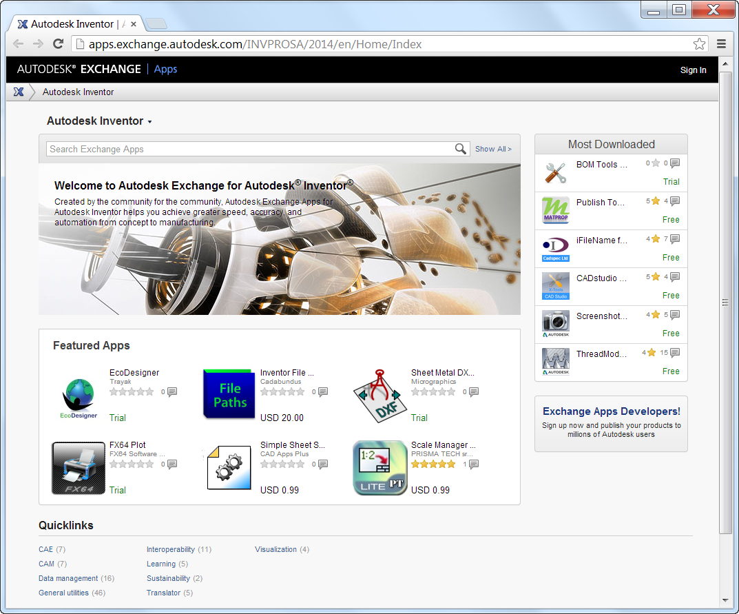
The Inventor App Site


Much like the application stores most of us have used for our mobile devices, the Autodesk version has utilities for many Autodesk programs, such as AutoCAD, Autodesk Inventor, and Autodesk Vault.

The reason I've decided to talk about this site is that I found a nice little utility I liked, one that I'll definitely be saving for the future. 

It's called "Inventor FeatureMigrator", and it's what it does that makes it interesting.

It can take an assembly level feature, and transfer it down to a the parts that the assembly level feature passes through. 

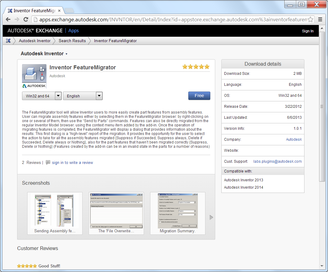
The Feature Migrator on the screen

I've been asked if there's a way to do this many times, and the answer has always been "no".  Now, with this little free utility, it's not! 

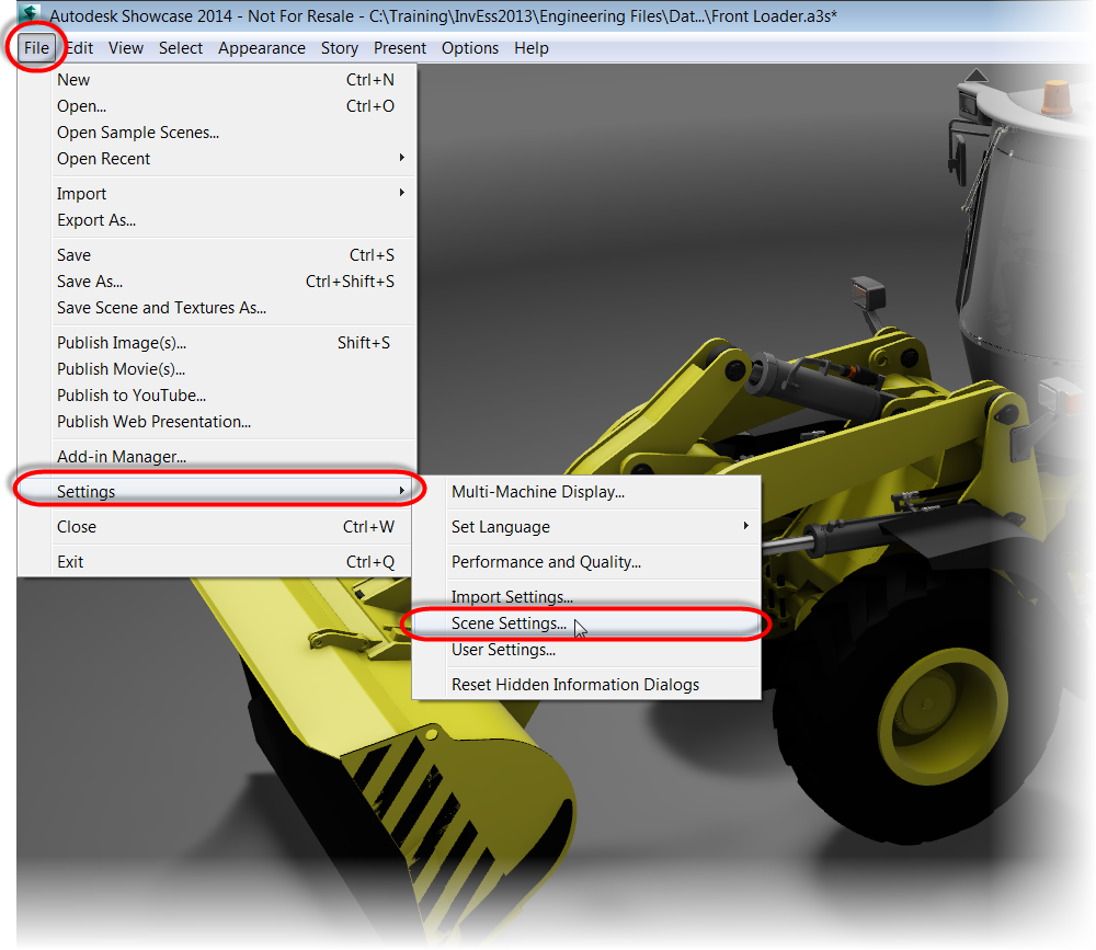
The first thing I did was download it from the site, and install it by clicking on the downloaded file.


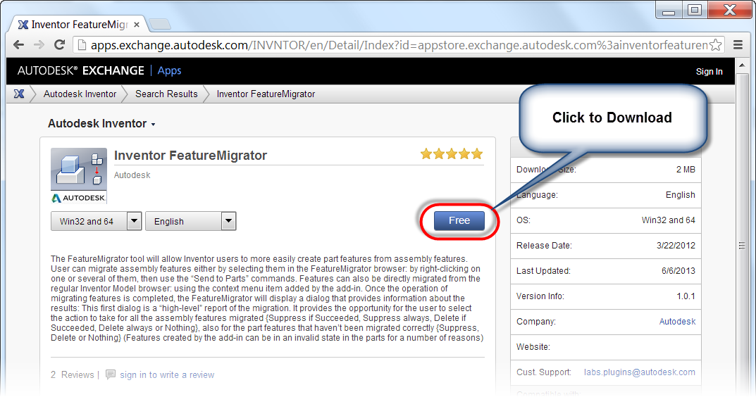
Downloading the app.

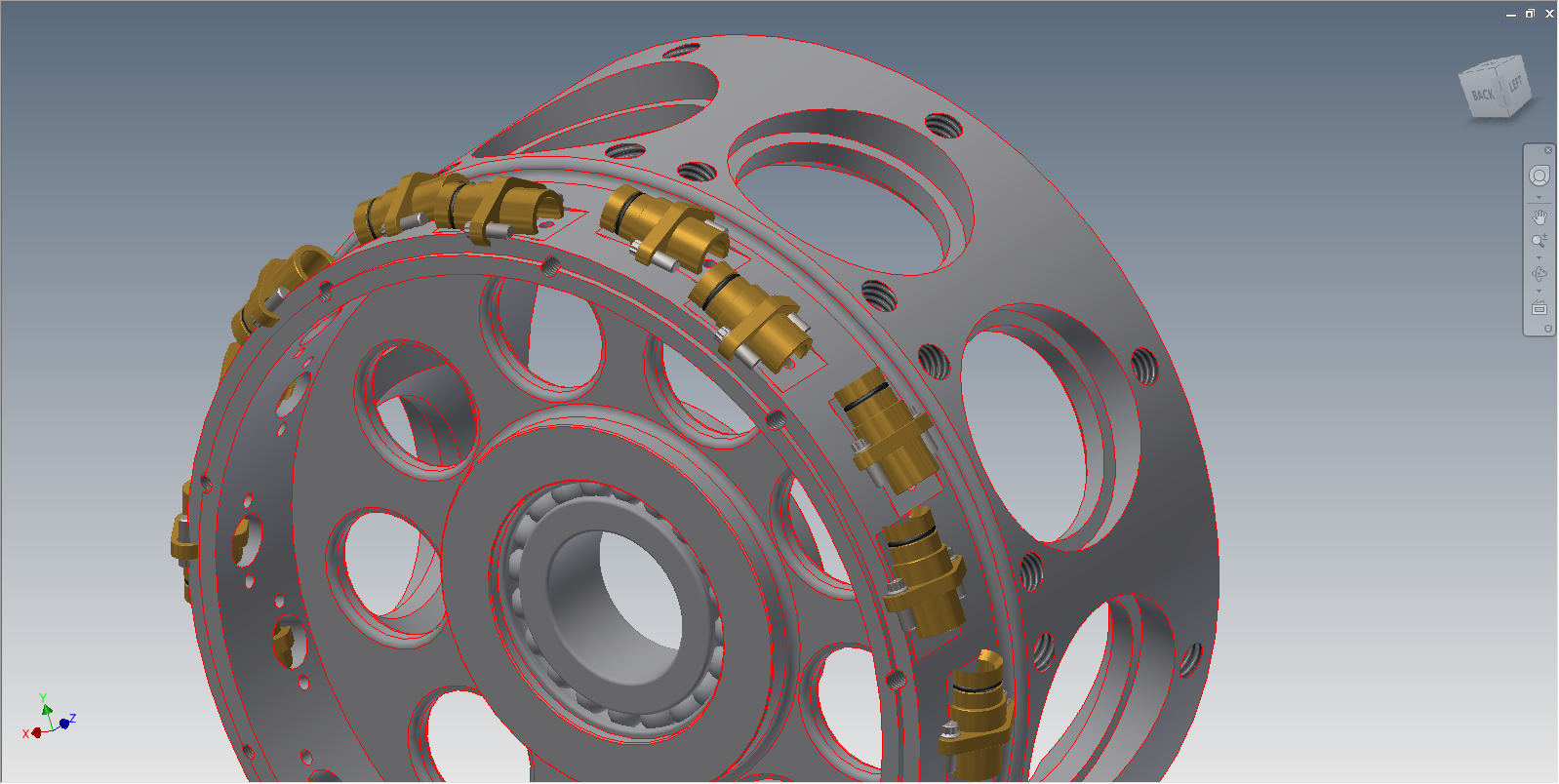
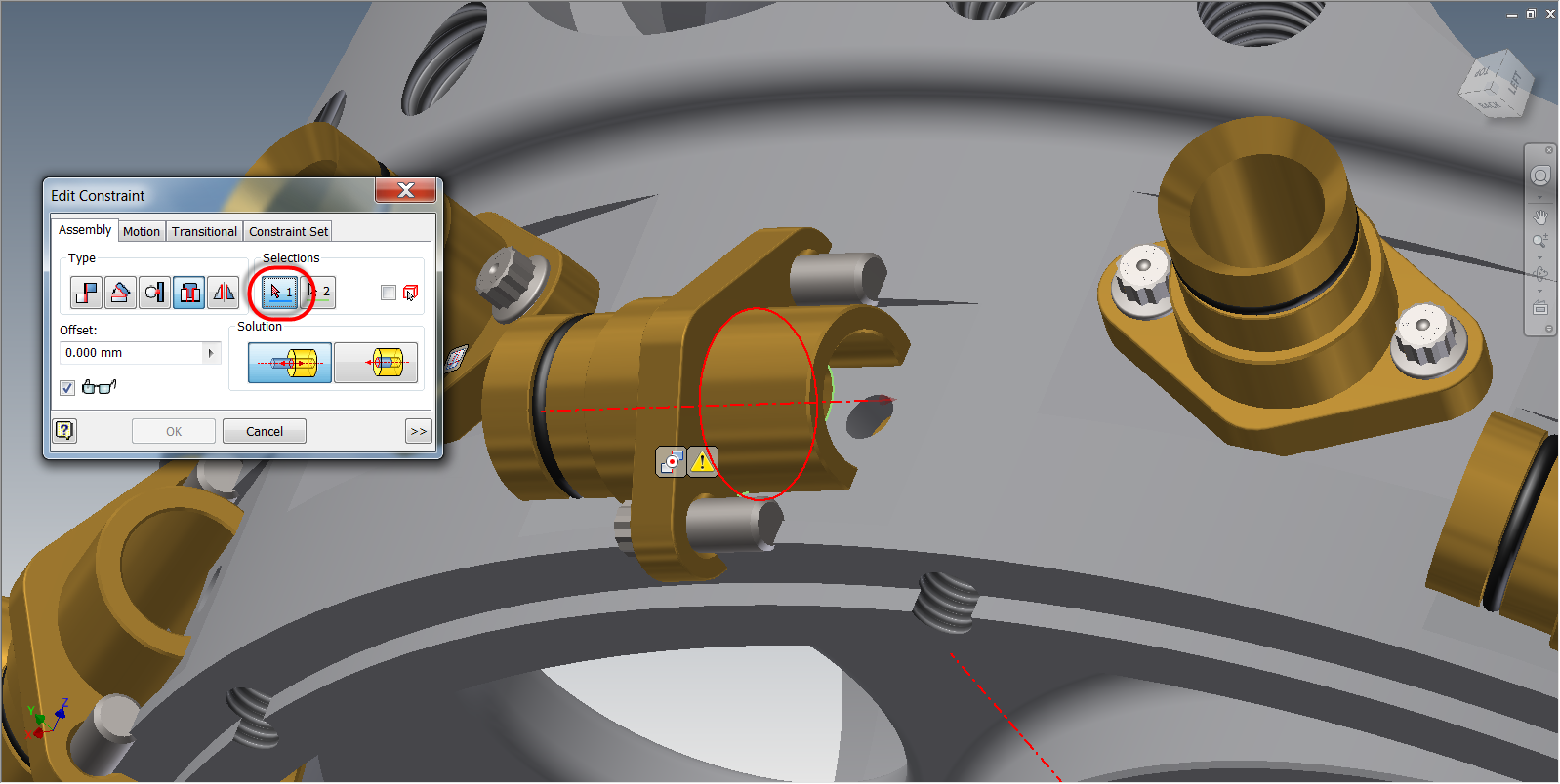
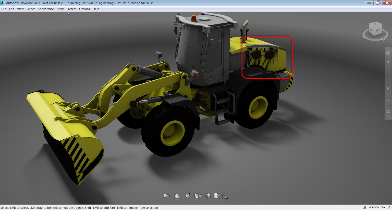
Once the app is installed, I'm ready to use it.  Here, I'm using an assembly of three components, with a slot placed through all three of them using an assembly level feature.

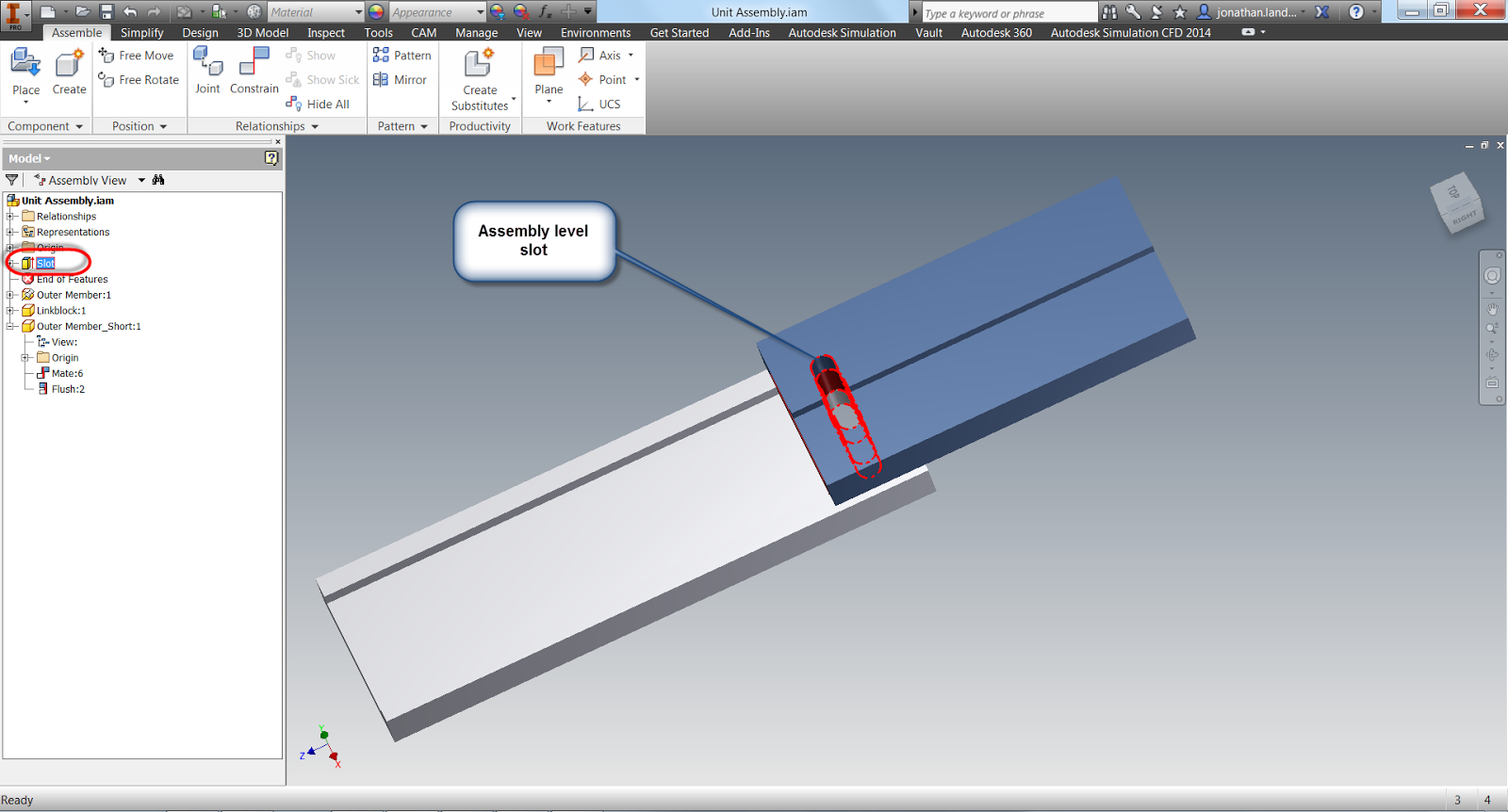
Three components with an assembly level slot punched through them


At the moment, Inventor looks much like it always has. 

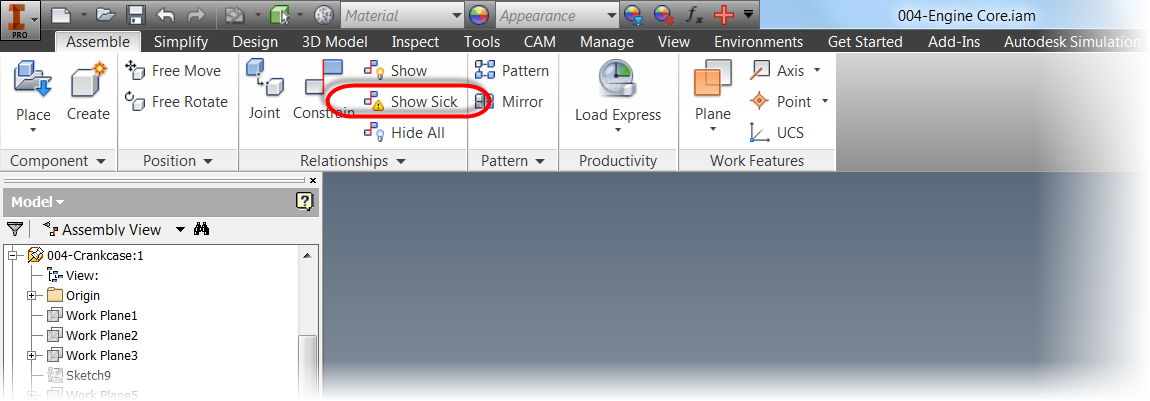
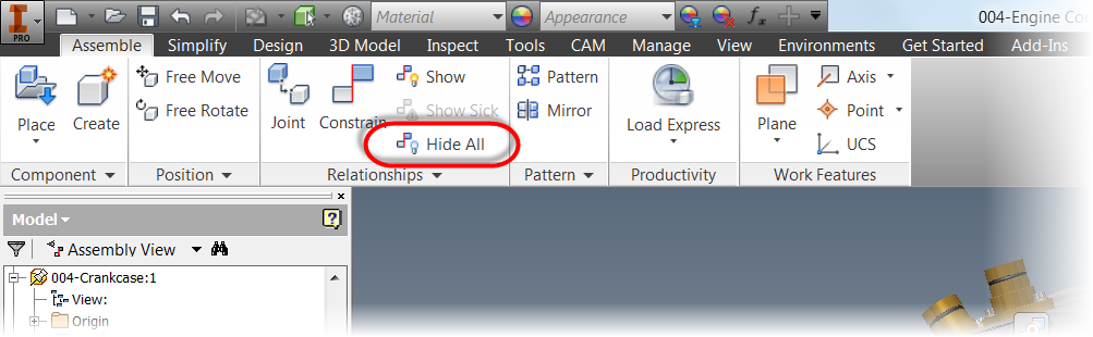
But, once installed, Inventor FeatureMigrator adds a button to the Tool Ribbon in the assembly file.  
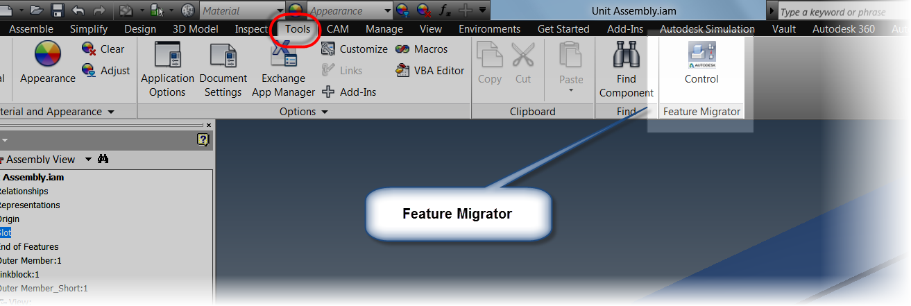


Finding the tool.

Clicking on this button starts the tool, which appears as a browser style window inside Inventor.

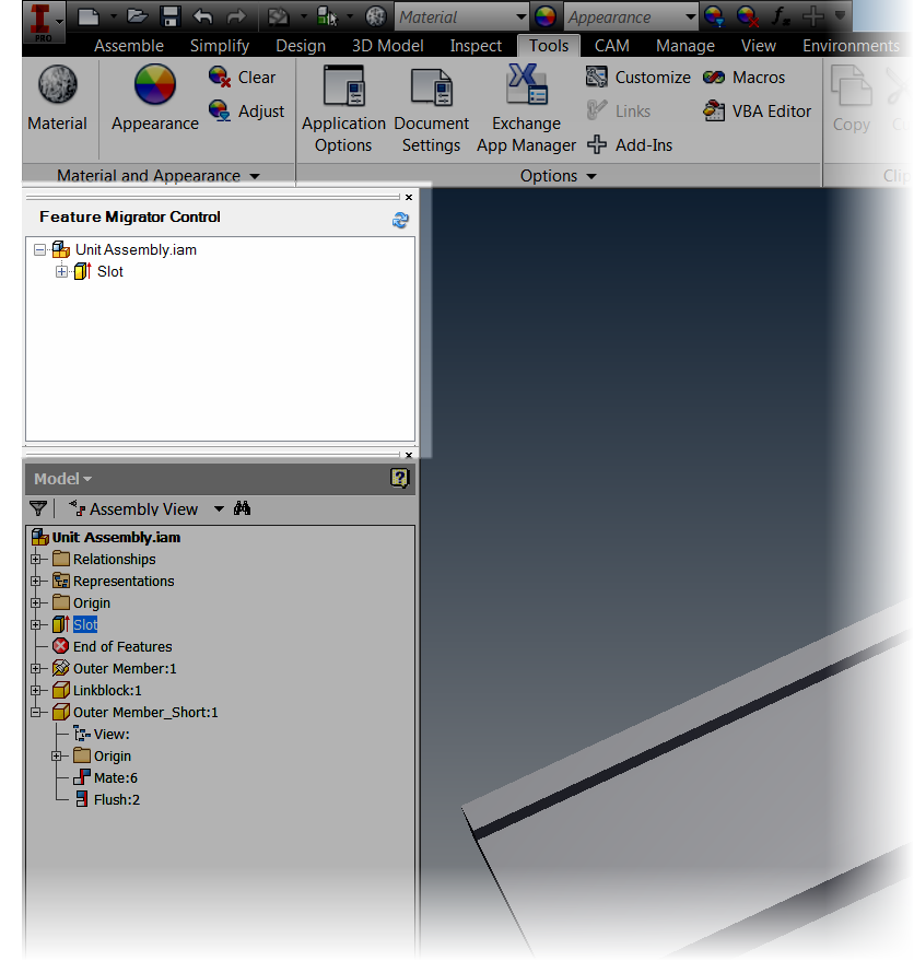
The "Browser Window"


Here I can see the assembly level features that are applied to this model, in this case, it's just a single feature I've named "Slot".

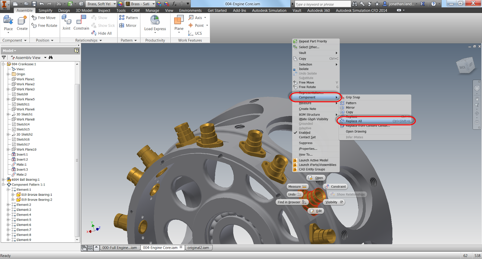
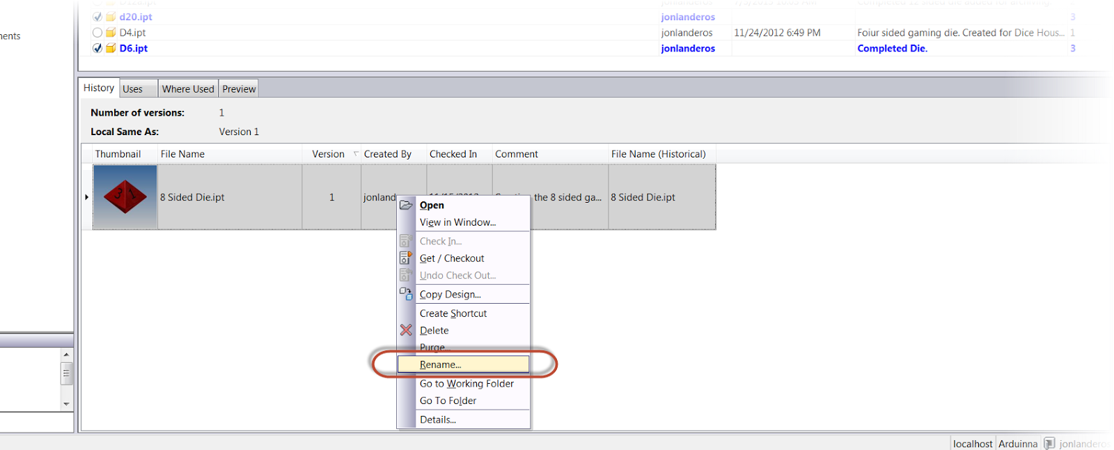
To start the process,  I right click on the feature I want, and choose "Send to Parts". 

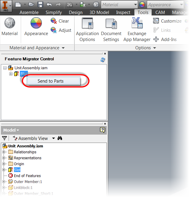
Sending the features to parts

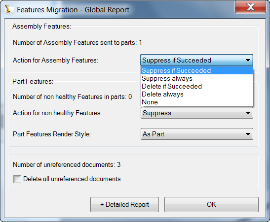
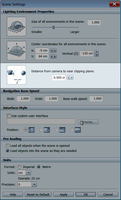
A dialog box will appear that has options for what to do with the translated assembly level features, such as options for suppression or deletion.  There are also options for how to handle "non-healthy" part features, even what render style to use on the part features.

The Translation Report

I can also click on the "Detailed Report" button to see more info on the translation.
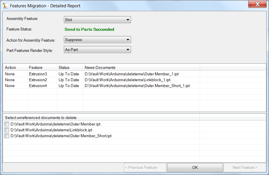
The Detailed Report

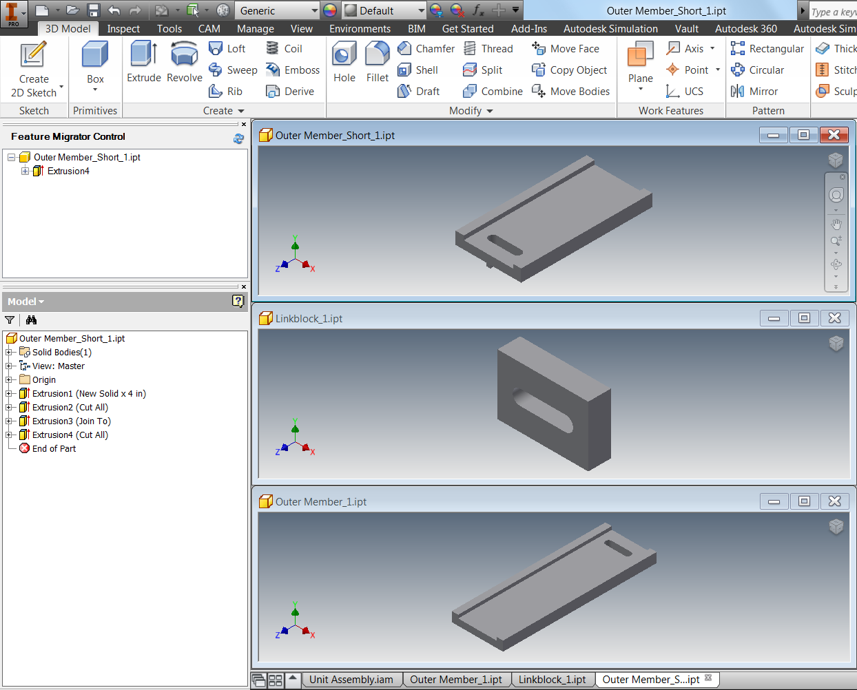
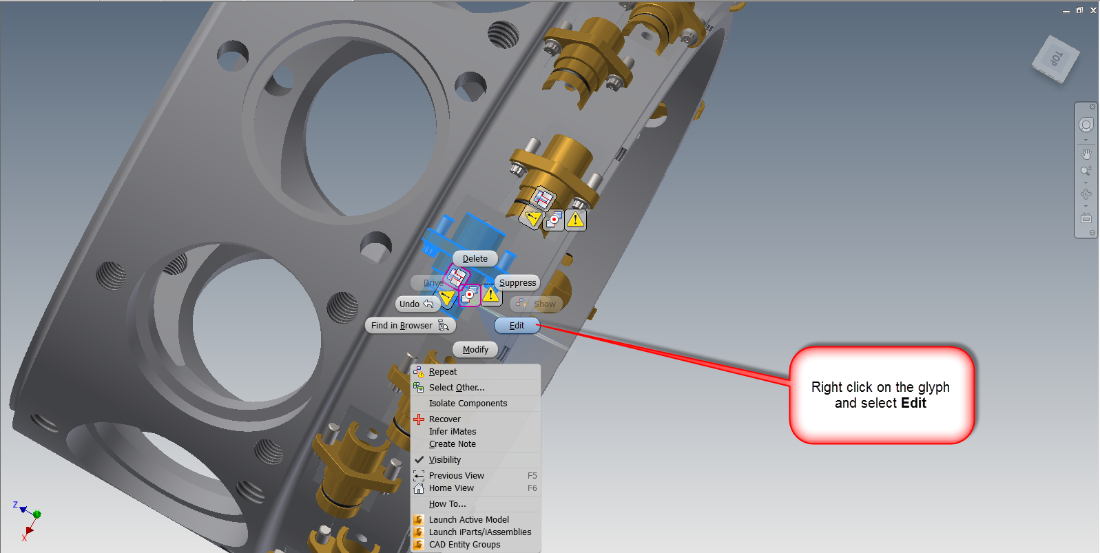
Hitting OK will complete the process.  The Slot I created at the assembly level is now pushed down to the part level.  To confirm this, each part can be opened and checked.


There are a couple of interesting quirks, in this little utility.  They don't bother me, but it wouldn't be right for me not to mention them.

1) It creates new copies of the components it affects, adding a "_1" to the filename.  I presume this is to make sure that sweeping modifications when a part use across multiple assemblies is modified. 

2) The sketches it creates aren't fully constrained to the new geometry.  So it may be beneficial to constrain (or fix), the geometry in each part.

For me, these are things are just curiosities for the advantages I gain, but I leave it for each user to decided.  If you think this tool is useful, Swing by the Autodesk Exchange App website and take a look!

I also like the Feature Recognition and Thread Modeler apps, so feel free to take a look at those too! 


Sunday, August 11, 2013

Showing and Fixing Sick Constraints in Autodesk Inventor 2014

“For this relief much thanks; 'tis bitter cold
And I am sick at heart.”
William Shakespeare

Once again a busy travel week has made my life hectic enough that I'm not able to create the video that typically goes with most of my posts. 

But with another busy week ahead, I've decided to press forward and create a text only post to describe a new feature that I've had a chance to use to great effect in Autodesk Inventor 2014.

That feature is Show Sick Constraints

As some may know, I've been slowly trying to rebuild a 9 cylinder radial engine in Inventor.  I found the original model on GrabCAD in Solidworks and several neutral projects, and decided to take it on with a long term goal to rebuild it completely in Inventor. 

The entire engine. This one is a Parasolid model imported into Inventor


I work on it here and there, so I suppose it's going to take a long time to finish it! 


One challenge I encountered was a simple one.  I was assembling bronze bushings into the engine core, there were two per cylinder, and 9 cylinders total.  So an Associative pattern readily took care of this.


The components.  The bushing is placed.  I need to change this to a subassembly containing the bushing and bolts


However at this moment I realized my mistake.  I had meant to put in a subassembly containing the bushing, and the bolts. 

However, in my haste, I had only put in the bronze bushing as a part. 

This was easy enough to fix.  All I had to do was to switch my selection filter to Select Part Priority.


Then I selected one of the bushings, and use Replace All Components to switch to the assembly I had intended to put in.


Replace All Components will let me change out all the bushings.
It let's me browse out and get the assembly I had intended to place, but now I have a problem.  The constraints have broken, and I have to fix them.  There's four, two for each bushing I had placed.  The other sixteen aren't a problem, once I fix the originals, they'll fix themselves.


The bushings are rotated sideways because the constraints are "sick" and need to be fixed.


But now I have to find the constraints......

Fortunately, Inventor 2014 has a new function called Show Sick Constraints.

The Show Sick Constraints icon

By clicking this icon, the sick constraints are graphically shown as glyphs on my screen.  I don't have to fish through the browser to find which they are and address them.

The Sick Constraint Glyphs.
Now I can select one of the glyphs, right click, and choose Edit

The screen capture is a little busy, but right click on the icon.
The Edit icon brings up the Constraint Edit screen.  Now I can re-associate the constraint that broke on me.

Note that in the screen shot below, I've already fixed one bushing.

I just click the icon, and select the geometry I want the constraint to act on.


Fixing the Insert Constraint

Fixing the Mate Constraint
Once all the constraints are fixed, I can now see that the rest of my pattern has reoriented itself too.

The engine core with the correct assembly
The constraints, now repaired, still show their glyphs on the screen. Now I can use the Hide All Constraints" icon to remove the glyphs.
All done!


Hiding the glyphs.

After clicking the Hide All Constraints icon removes all the glyphs on the screen, and now I'm back in business!

If you have Inventor 2014, or you're thinking of going to it.  Take a look at this feature!  It's well worth it!


For other new features with Assembly Constraints in Inventor 2014.  Check out my previous post on Constraint Relationships.

Acknowledgements:

I have to thank Dave Goetsch for sharing this file on GrabCAD,  Without his work, I wouldn't have been able to write this post.  Check out his excellent work on this and other projects. 


Monday, August 05, 2013

A Quick Trick - Selecting All Occurrences in an Autodesk Inventor Assembly

I have called this principle, by which each slight variation, if useful, is preserved, by the term of Natural Selection.
Charles Darwin

Note: The assembly I was working on today isn't one I'm free to share, so I'm using a "stunt assembly" as a stand in.  Bear with me!  

I'm still out here working far from home in Minnesota, where I'll be the rest of this week.  And while I don't have time to create any big posts, I can post a quick tip for today.

One I used just today.

I was working on an assembly that had several components that were very similar.  They looked so close that they may have been a second copy of the same component, or a different component entirely.

To make it even more interesting, there were several components that were similar, so it wasn't even an either or, it was one of many.

So how can I quickly determine which components belonged where? 

Sure, I could go into the Assembly Bill of Materials and see how many instances of the component I see, and while that works great, it doesn't always give me what I need.

One way of checking how many components there are in an assembly.
So what's a quick alternative? 

I'm going to right click on one of the components I'm curious about, and choose Selection>Select All Occurrences.  Just like I've done with the shock assembly pictured here.

Right clicking and choosing "Select All Occurrences"


This will select all copies of of the same component on screen.  This quickly tells me how many components are similar visually, without leaving the modeling window.


Both assemblies highlight, telling me they're the same assembly placed twice

Now I can see that both shocks are actually the same assembly used twice, instead of two very similar, but different assemblies.

As an added bonus, I can now change visibility, delete, and replace the components, among other commands, because I've already selected the components I need.

To be fair, I'm not saying this isn't a replacement for other methods, like using the Bill or Materials to check how many components are in an assembly, but what it can do is check to see if "this component is the same as that component", when a quick check is needed.

So give this a try and add it to your bag of tricks.  When I was working with that assembly today, it was a big help! 

Sunday, August 04, 2013

A Blog Delayed this Week.

I had high hopes for writing a post this week!  But I had to take a business trip to Minnesota, and due to a couple of delays, I got in just late enough to clean up and get to bed!

So look for a post a little later this week!

And to hold you over, here's a video of the Planes of Fame F4U Corsair starting and flying from this weekend.

Apologies for the shaky camera work.  It was the best I could do with my little point and shoot camera! 

Thursday, August 01, 2013

Getting Rid of the "Black Streaks" in an Autodesk Showcase Scene

I believe in the kingdom come
Then all the colors will bleed into one
U2 - "I Still Haven't Found What I'm Looking For"

Sometimes, there really is "one magic" setting that can obtain the desired result.  In Autodesk Showcase, I've found that one of these is setting the clipping plane.

Sometimes, when a model is imported into a Showcase scene, black triangular streaks will appear across the model.

What are those?  They're not supposed to be there!


They shouldn't be there, they're not right, and they're ugly.

They're actually caused by Showcase not being able to sort the faces.  The back face is actually bleeding through the face in front of it.

Fortunately, they can be easily cleaned up with just one setting.
 

The setting is found in File>Settings>Scene Settings


Getting to the setting I need

Once the dialog box opens, the setting I'm after is: Distance from camera to near clipping plane:

The setting to change is highlighted.
By increasing the number, the distance to the clipping is changed and the faces can set the correct order.


Much better!

In this case, increasing the setting to 2.000cm makes everything as it should be.  Of course different scenes may require different settings, so if you if you're working with your own scenes, you may have to try a couple of different numbers.

But just that setting alone, can make a huge difference in how a Showcase scene appears in the end.

For a fantastic explanation of this, take a look at the video below created by Marion Landry.  She's the person who originally taught me this great trick, and she's definitely got the definitive video in my opinion! 


Sunday, July 28, 2013

An Introduction to Autodesk Configurator 360

You're giving a gift, so finish that process. If you configure it for them, your sweat is in it.”
Alfred Huger

Back on July 9th, 2013, Autodesk announced Autodesk Configurator 360.  It's a cloud based configurator where Autodesk Inventor files can be hosted and configured given parameters and iLogic rules online. 

All that's required is to upload a model to Configurator 360, select the desired options, and release it into the wild.  There are even options to control who can access the configuration.

So with all this cool stuff, how is Configurator 360 accessed?

First, you need something that can be configured.  In this example, I'm using an assembly powered by iLogic.

This is a template for a router jig for use in wood working.  This is a template that can be copied, then modified to fit the part it's going to cut.  The iLogic rules drive the size of the base, and the position of the handles and stop on the base.


The router jig template, showing the iLogic form that drives it.


Next,   access to the Configurator 360 site is needed, which isn't difficult, a 90 day trial can be obtained here. 


The Configurator 360 site

Once a trial is obtained, I can go ahead and log into Configurator 360 site, I'm going to take this folder, in a zipped format and upload it to my Configurator 360 site.

I upload my design by choosing the Designs tab, and clicking the New Design icon.

Adding a new design to Configurator 360


The screen to upload the file will appear. I'll have the option to name the project, choose a format to upload the files in (*.iam, zipped *.iam, ipt, or zipped ETO). 

Adding an assembly to Configurator 360

Now, all I have to do is click the upload icon to upload the file to Configurator 360. Note that at first, the webpage may have to be refreshed to get the files to appear.


Once the webpage is refreshed, the Configuration appears, and it can now be edited by selecting the icon in the picture below. 


The first tab that appears is the "Access" tab.  This tab provides a place to change the display name, create a description, and control access permissions to this particular configuration.


Clicking on the Parameters tab, options to control parameter name, order, and if a parameter is read only or not can be set here.  Here, parameters can be set to read only, or minimum or maximum values can be set.


Now, that this is accomplished, I can make the configuration available. for users, where they can change, values, and download files as needed, to make use of the configuration that has been provided to them via Autodesk Configurator 360.


So have a look at the configuration I created at the link here, and see for yourself if something like this might be helpful to your business..

If it is, have a go at the free trial on the Configurator 360 site!

And take a look at the video below!


Sunday, July 21, 2013

Points for Style - Creating an Offset Workplane and Sketch in One Step in Autodesk Inventor

“You can't do sketches enough. Sketch everything and keep your curiosity fresh.”
John Singer Sargent

Some of my favorite tricks in Autodesk Inventor are the simple ones.  They may not be flashy and they may not save hours of time, but they're nice little tricks that just make the day to day operations flow by a little smoother.

One of these, is the ability to create an offset work plane and sketch at the same time.

Typically, to create a sketch on an offset work plane there are a few clicks involved.

First, I have to start the work plane tool, and create my offset work plane.

Creating the workplane

Next, I have to place a sketch, on that newly created work plane.

Creating a sketch on that work plane

There aren't a lot of clicks involved, but it's always nice if there's a way to do it with even fewer clicks. 

How can that be done? 

Instead of going to the Work Plane tool, I'm going to start the 2D Sketch tool directly.

By clicking and holding on the planar face I want to offset from, I can drag the offset work plane, and create both the sketch, and the plane at the same time.


It's a simple thing, but it really does make things flow a bit more smoothly.

Give it a try! 

And take a look at the steps shown in the video below!


Sunday, July 14, 2013

Making the Work Plane Tool in Autodesk Inventor "Stick" and Stay on Until You're Done!

“The possibility of stepping into a higher plane is quite real for everyone. It requires no force or effort or sacrifice. It involves little more than changing our ideas about what is normal.”
Deepak Chopra

Today is a quick blog post.  I broke my routine today and took a road trip to Camarillo, Ca.  and cruised a picturesque little town from my childhood. 

I also took some time with the Southern California Wing of the Commemorative Air Force, and saw a few of the incredible aircraft they have at their facility.


Here are just a couple of the aircraft that make their home at Camarillo Airport.

d

A Curtiss C-46 Commando (yes that's my finger in the picture)

A Griffon powered Spitfire MkIV. 


It was a nice change of routine, but it did hurt the blog post!    But nonetheless, here is a short post!

One setting I love to change in Autodesk Inventor is the default behavior for work features like Work Planes, Work Axis, and Work Points

In Inventor the default behavior is to place one work feature, then exit the tool.

So if you want to place more than one, you have to restart the tool and place the next work feature.

What many users out there may not know, is that this behavior can be changed.  There's a way to make the tool "stick"  so as many work features can be placed in succession without having to restart the tool every time.

In order to make the tool "sticky" use the steps below.  I'm going to use a Work Plane, but it's the same steps for Work Axis and Work Points.

1) Start the tool.  In this case, Work Plane


Starting the Work Plane Tool.
2) Now that the Work Plane tool is active, right click and choose Repeat Command.  Make sure the option is checked as shown in the screen shot below.


Make sure Repeat Command is checked


And it's all done.  This setting will stay on until it's changed, and from this point forward, the Work Plane command will stay active until cancelled.


So give it a try and see what you think.

And for the video portion, here it is below!


Thursday, July 11, 2013

Autodesk Configurator 360 - Something new from Autodesk

“You're giving a gift, so finish that process. If you configure it for them, your sweat is in it.”
Alfred Huger

Today, it's just time to talk about something from the news desk. 

As of yesterday, Autodesk has released Autodesk Configurator 360

This cloud application allows the user to upload Autodesk Inventor components, select key parameters, and let someone, such as a customer, configure the components via a cloud application. 

It's brand spanking new, so new it's still got that "New Software Smell".  So I can't say that I know all of it's ins and outs.  But here's a video to take a look at. 


It comes with a 90 day trial, so it might just be worth taking a look at! 


Sunday, July 07, 2013

Recalling an Old Filename for a File Renamed in Autodesk Vault

History will be kind to me for I intend to write it.
Winston Churchill

One of the nicest functions of Autodesk Vault is the ability to rename a file easily, as well as track the versions of files, and the history of files. 

But what happens if after renaming a file, it becomes necessary to recall the previous name?

Fortunately, Vault as a field designed for just this purpose.

It's called: File Name (Historical)

When this file is added to the Preview Pane in Vault, the old file name (before it was renamed) will be seen.

Now that we know that, how is the field added to Vault Explorer?

First, right click on the title bar in the Preview Pane, and choose Customize View.  Don't use the Browser Pane.  This one only shows the current file, and it's the files in the past we're after.


Customizing the view

Once the dialog box appears, click on the Fields icon.

Click on the Fields icon


Locate the File Name (Historical) field and add it to the title bar.


Locate the field and click Add
The field will move to the right column

 Once the field shows in the dialog box, click OK to close the dialog box, and click Close on the dialog box after that.

The and the field will now show in the title bar.


The field showing in the pane

But since the file "8 Sided Die.ipt" only has one version, there isn't much to see.  However, now I'm going to rename the file to "D8.ipt" to match the naming convention for the other dice I have in Vault (D4.ipt for a 4 sided die, D6. for a 6 sided die, etc.)

To rename the file, I'm going to right click on it, and choose Rename, and step through the wizard to rename the file.


Right clicking to rename the file.

To see all the details for renaming a file in Autodesk Vault, they can be found in my earlier post here.

Once the file is renamed, I'll see two lines in the Preview Pane.  The File Name column will show the current file name, but the File Name (Historical) field will show what the name of the file was before! 

The history is visible, right there!

And for one last tip, try searching for the old file name.  Since Vault still remembers the history, the file can still be located by the old file name!

Searching by the old file name
And now, for the same steps in a video version, take a look at the video below!

<iframe width="545" height="409" src="//www.youtube.com/embed/A1GbPbtn7zo" frameborder="0" allowfullscreen></iframe>

And on a final note, if you're interested in the dice models that are used in this example.  You can find them at my GrabCAD site here!