Find us on Google+ Inventor Tales

Tuesday, November 25, 2014

A Use for Inventor's Sketch Constraint "Relax" Mode

“Try to relax and enjoy the crisis.”
 Ashleigh Brilliant 

Sometimes, it takes the right circumstances to find a good way to use a new feature in Autodesk Inventor.

The new Relax mode in Inventor 2015 fell squarely into this bucket.

When it first came out, I was frankly a little unsure of the new tool.  It's my nature.  I just find myself wary of any tool that is "too automatic".  I'm just type "A" enough to not like it when too much is done for me.  I circle them like a cat sizing up a potential meal.

But I've also learned that there is a time and a place for these tools too.  Experience has taught me to never dismiss a new function too quickly.

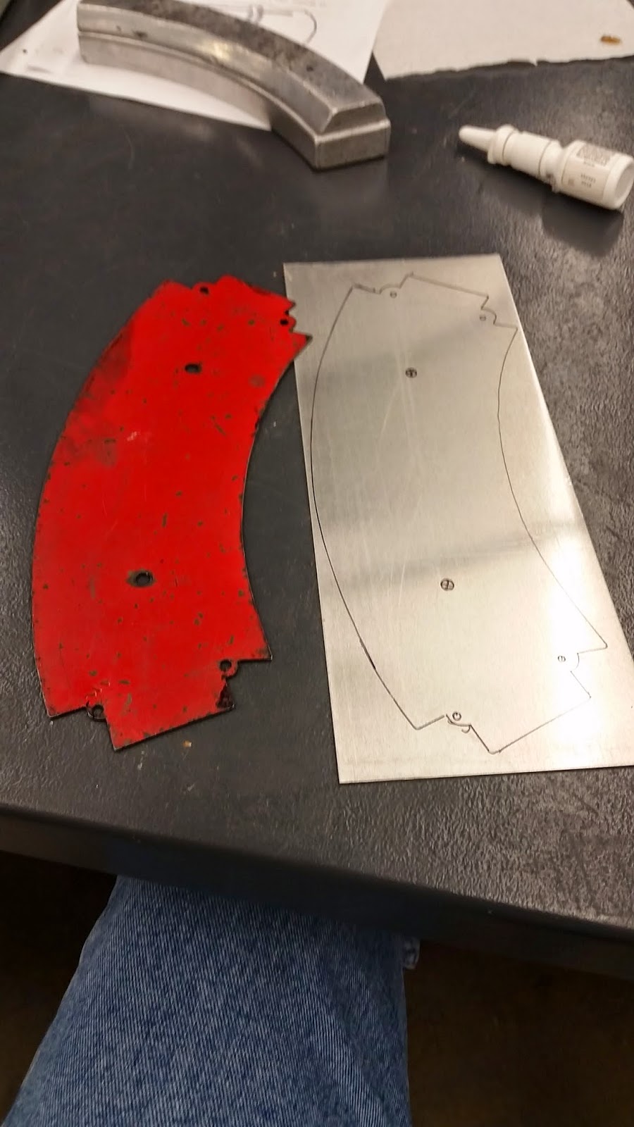
In my case, I was rebuilding an aircraft instrument panel in Inventor.

Originally, I had created it as a test to benchmark how text affected the speed and file size in Inventor.  To do this, this, I created the cutouts for the instruments as extruded borders with text inside.

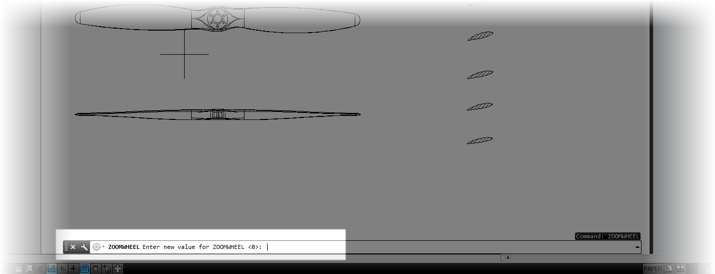
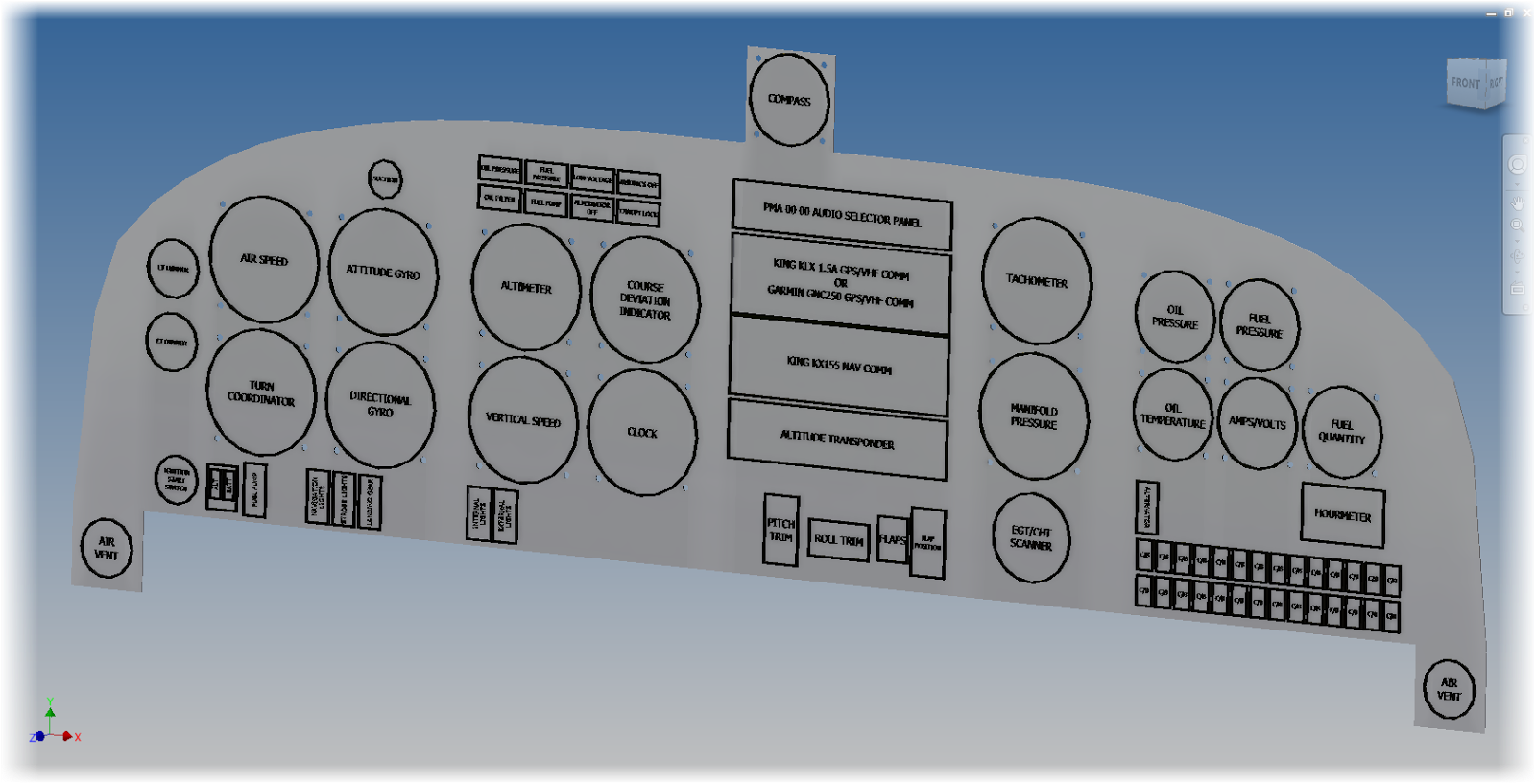
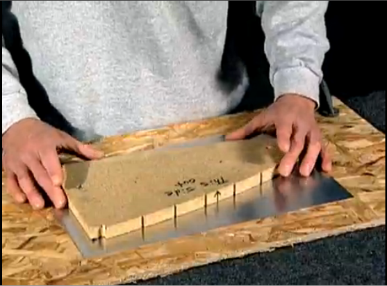
A sample of the original panel.  There were no cutouts for instruments,
but this was part of a test and not meant to be "real" at this point.
Not accurate as a part.  But perfect for the benchmark I was creating!

But once I had done that, I wanted to create a more accurate representation of the panel.  This meant deleting the extruded  borders, and recreating them as cutouts.

But as I did that, I ran into one issue.  Part of the sketch that I had removed had anchored the text that I had placed.  Now the geometry was disassociated.


I could delete and recreate the sketch, but I didn't want to try to retype all that info again.

But what I did find was able to delete constraints to free the geometry and reattach it to other geometry,  In some cases, this meant deleting four co-linear constraints, and recreating them all over again.  This is what I would have to do with these circuit breaker cutouts, for example.


While it wasn't a huge pain for a few of them, there were a ton, there was a lot to do, so how could I make this task go a little quicker?

Well, if you guessed that I used the "Relax" constraints mode that's new to Inventor 2015, you would be guessing correctly!

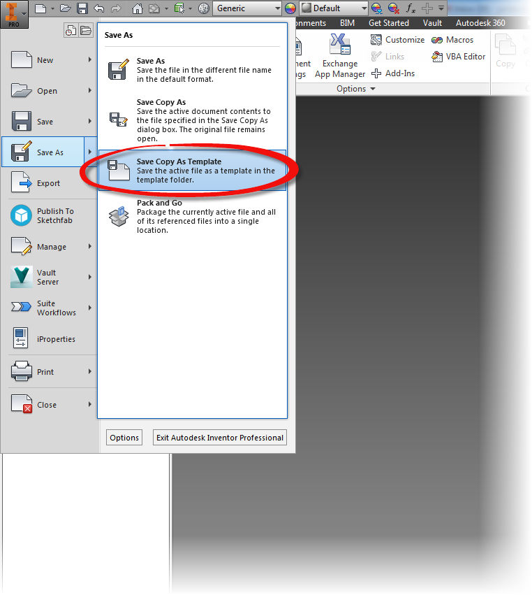
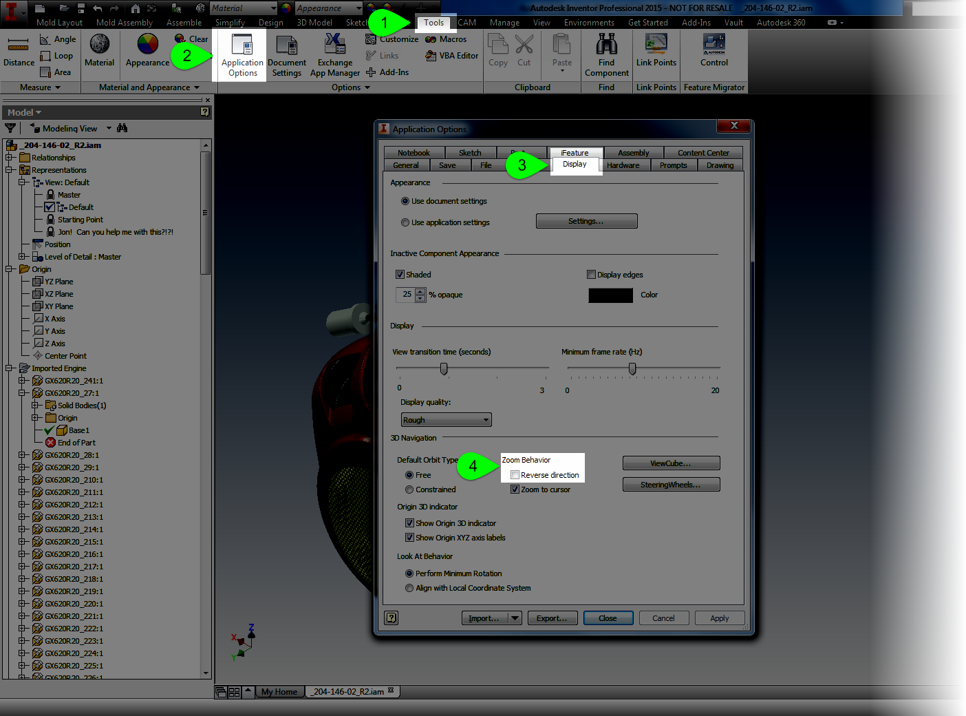
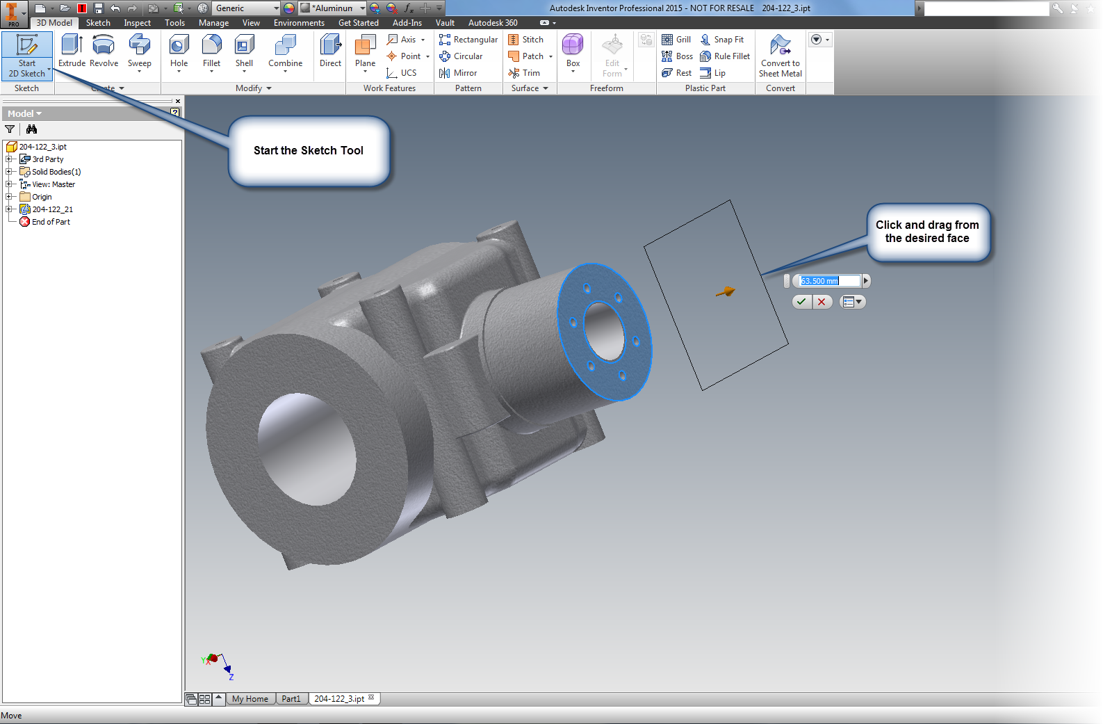
First, while editing the sketch in question, I  turned on Relax Mode,  It can be found at the status bar on the bottom of the Inventor drawing screen.  You can also use the hotkey "F11"


Once that was on, all I had to do was grab the text and drag it.  The constraints would automatically be removed, and I apply the new sketch constraints right away.


Is it a small thing?  Perhaps.  But over time, it did make fixing the panel a lot easier!

A simple thing?  Perhaps.  But it can be the simple things that matter.


Thursday, November 13, 2014

Did You Know You Can Use the End of Part Marker to "Compress" an Inventor File

“The question is, what's the best way to do this? There may not be a one-size solution to the question.”
 Peter Gore

Today I wrapped up some basic benchmarks for extruded text versus sketched text in an Autodesk Inventor part model, and I was getting ready to e-mail them out for some testing on external systems.

First, what did I use for the test?

The files I created were from an instrument panel for light sport aircraft from the RV series.

I recreated the panel from an image, and created the instrument identification first as extruded text.

The panel with extruded text

In the next panel, I created a panel with the same text, but this time, the panel the text was created as sketches, and not extruded into 3D extrusions.

The panel with sketched text.  You can tell by the projected sketch lines, which are magenta.

The challenge?  The panel with the extruded text was nearly 13 MB!

12.7 MB.  That's big! 
By comparison, the panel using just sketches was less than 2 MB!

1.64 MB.  Nearly a tenth the size!

First, let's take a moment to ponder that.  If you're creating a lot of text, consider leaving it as sketches. These two models show a big difference in the size, and that can affect performance, especially if there's a lot of them.

But there was also another challenge I was facing.  How can I e-mail the files?  Together, these files are flirting with 15 MB.  That's big enough to cause problems with some e-mail systems.

Sure, I could zip the files, but there's another way to "compress" an Inventor file.

Locate the End of Part marker.  It's also known as End of Folded if you're using a sheet metal part.

Right click on the marker and choose Move EOP to Top (or  Move EOF to Top for sheet metal parts).

Locate the End of Part marker.
This pushes the marker to the top, and all the a feature in the part are suppressed.

The EOP at the top, and the features suppressed
After compression, the part with extruded text was a mere 2.41 MB.

A big change from 12.7 MB

By comparison the panel using Sketches was 1.01 MB.  Not as drastic as the larger file, but substantial nonetheless.


A smaller change, but still about a third. 
Having that trick can make it much easier when moving large part files back and forth.

When the recipient gets the file on the other end, just right click on the EOP/EOF marker and choose Move EOP/EOF to End.

How to get it back. 
This can be a nice way to "compress" an Inventor file without having to use zip files.  So when you're sending part files around, take a look!  It's worth a glance.

Oh!, And if you have an unsuspecting coworker, rolling the EOP to the top of their part when they leave their computer unattended has been known to be an "April Fools Trick" in the past.

Not that I condone that..... Or I've ever done that....

*************************Edit 17-November-2014*************************

Thanks to Clint Brown of Cadline Community for sharing a nice bit of iLogic code that will rollup the EOP marker and put it in an email for you.

It's definitely work taking a look at!

Have a look by clicking here! 


Thursday, November 06, 2014

Autodesk Vault 2015 Service Pack 1 is Out!

It's that time again, a new Service Pack for Autodesk Vault.

It can be downloaded by clicking here!

So what are the steps to install it?

Without going any further, it's all spelled out in the readme files that are included with the service pack.  And no matter what you do with this blog post, you should be reading those!

This is particularly true if you're working in a replicated environment.  The steps in this post are the steps for a single site update!

These are the files you should reference!
With that being said, let's begin.

There are some steps that you should always do, when updating Vault, particularly with the server. It's just good standard operating procedures, and good practice

1) First make sure you have a backup.  

In reality, you should be checking this already, but this is a good time to make recheck and make sure.  There's always the chance of something unforeseen going wrong!

I've never had a service pack fail to install, but I've talked to people who've had power outages occur right in the middle of an install.  How is that for bad luck?

Be a hero, have a backup

Stranger things have happened
photo credit: Rogan via photopin cc

2) The system will be down for a while.

Don't plan on running this upgrade on the server in the afternoon just before a project is due.  The service pack migrates the database, during which time the Vault will be closed for business.

Don't be the guy calling tech support and end up being told "Yeah, dude.  You're just gonna have to wait for that to finish.".

These are common steps in planning, but they're often overlooked, and I think they're important to mention.

Now, we get to start the service pack process!

First, open up a command prompt by typing CMD at the windows start window


Once the command prompt opens.  Type IISRESET.  This bounces the IIS service.


Now, you can finally click on the *.msp file to start the Vault Server service pack.

You may launch when ready


Now it's just a matter of clicking through and waiting.  It's a good idea to follow the recommendations

Ready, set...

Now the service pack will install.  Give it time to finish.


Go! 

After a bit, the service pack will tell you it's done!

All done!  Or is it? 


Once the service pack is installed, open the ADMS Console, and make sure the databases are migrated.

Vault will ask you several questions during this series of steps. First, it begins a before you log in.


Migrating before logging in
Next, Vault will ask you to log in, and which Vaults to migrate.  I've never done anything but pick all.

What libraries to migrate

Now, there's more migration!


You might think you're done, but if you have custom content libraries stored in Vault, you're going to see a few more questions.  Vault is asking you if you want to keep copies of libraries for multiple versions of Inventor.  If you're not using old versions of Inventor, this is your chance to get rid of old libraries.

What libraries do you want to keep

Clicking OK on this dialog box brings up yet one MORE dialog box.  What I call, the "are you sure?" dialog.  It's a final confirmation to make sure that the clicks you've made are correct.

Are you sure that you're settings are right? 
Now, at long last, the screen we're hoping for.   Success!


So those are the basic steps.  Vault updates aren't that difficult with a little planning.

The next step is to move onto the clients installs.  Those are pretty easy, and while you should update the clients as soon as possible.  Those can be done at a much more leisurely pace.


Monday, November 03, 2014

How Precise is Precise? Changing Measure Precision in Autodesk Inventor

“Most of the most important experiences that truly educate cannot be arranged ahead of time with any precision.”
Harold Taylor

KETIV's AMA 2014 in Southern California is a wrap!  It was good to see everyone, and as much stress as it was preparing for the session I helped in, it was fun presenting again.

But out of that course came one question that I didn't know the answer to.

"How can you change the default measuring precision in Autodesk Inventor?"


The default measure location behavior
At the time, standing in front of the room, I didn't know the answer.  After all, I don't know everything!

But over the weekend, the thought would occasionally return to me.  I felt like there might be a way.

Finally, I had a little bit of inspiration, and decided to give it a try.

Opening up Inventor, I played a little bit of a hunch.  On the Tools tab, I located Document Settings and opened up the Document Settings dialog.

Using Document Settings


Once on the Document Settings dialog,choose the number of decimal places you want by changing the Linear Dim Display Precision (or angular if that's your preference).

Changing precision

Once that's done, the measure precision will change for this document.

Precision reset. 

But wait, I said default setting, right?   If you want to make this a default behavior, the final step would be save these settings into a template file.

One way would be to open the templates from their location, make the very same change, and save that file.  This would change the existing templates.

The other would be to start a new file, make any changes you want, and choose the Save Copy As Template option.


Save as a Template

Whichever you choose is up to you!

On a final note.  I know that there are those who might want a different functionality.  And that's okay!   Share your ideas on the Autodesk Inventor Ideastation!

Sunday, October 26, 2014

Scroll Wheels in Autodesk Inventor and AutoCAD. They can behave the same!


As the Autodesk Manufacturing Academy (AMA) gets closer, I find myself pretty busy.  But I still wanted to share a tip, even if it's short.

Here's a simple tip that sometimes comes up when I'm training my Inventor Essentials class.  It's most often encountered with users who have to constantly switch between Inventor and AutoCAD. 

"Can scrolling in Inventor and the scrolling in AutoCAD made to match?"  

That's right, by default, Inventor and AutoCAD don't scroll in the same direction.  I've been told that's because one program views the geometry as moving toward the camera (or user), the other one views the camera (or user) moving toward the geometry. 

I don't know if this is true or not.  But it at least sounds good. 

More importantly, there's a way to make them work the way an individual user (that means you!) can make each program match. 

First, in AutoCAD, type ZOOMWHEEL.   

Change the setting to 1 or 0.  Use whichever suits your preference. 

Type ZOOMWHEEL in AutoCAD

Now, in Inventor, go to Tools>Application Options>Display

Locate Zoom Behavior, and set that to the preference you like. 

Changing zoom behavior in Inventor

Everyone is a little different, but between these two variables, you can get them to do what you want, and get them to be consistent about it! 

In the meantime, I'm back to getting ready for AMA! 

Monday, October 20, 2014

Just for Fun, and Some Weary Humor Coming Out

I've still been in a loop of training, getting ready for training, and preparing for KETIV's AMA event on October 29th.

Like many people, I cringe at an overused buzzword.  I really cringe when I hear myself saying them.
So on a break, took some common buzzwords from the link here and created Star Wars equivalents of them.

Once again, Vader wins manager of the year.
Why?  Why not?  I just needed to have a little fun I suppose!

In any case, on a random whim, I decided to share them.  There's no "Inventorness" here today.  So feel free to keep moving.  Or, take a couple of minutes and enjoy my slightly warped humor.

Perhaps if enough of us start using them, we'll create a 'paradigm shift'!

  1. "Reach out" - "Force choke". 
  2. "Take off line" -"After we exit hyperspace
  3. "Shift our goal posts" - "Redeploy our stormtroopers."
  4. "Socialize documents" - "Set a course for Mos Eisley
  5. "Monetize" - "Make like Boba Fett."
  6. "Downsize" - "Feed to Sarlacc"
  7. "All in effort" - "Send the Death Star"
  8. "Accelerate" - "Jump to hyperspace"
  9. "Thought Leadership" - "Jedi mind tricks
  10. "Button up" - "Encase in Carbonite"
Like I said.  This is just for a little fun before I put my head back down and start working again.  Hope you enjoyed it, and I'm working on some more "real" blog posts soon. 

Do you have a few, feel free to add a comment! 

Thursday, October 09, 2014

Autodesk Inventor in Real Life - Tolar Manufacturing

“One man's "magic" is another man's engineering. "Supernatural" is a null word.”
 Robert A. Heinlein

This month is KETIV's Autodesk Manufacturing Academy event in Cerritos, Ca, and surprise, I've been pretty busy.

I have a couple of posts in the queue, but I just haven't quite had the chance to wrap them up.  But I work on them for a few moments when I can, so I hope to have them soon.

To tide everyone over a bit, I wanted to share a video from Tolar Manufacturing.  They've been using Autodesk Inventor for some time now to create their transit shelters, and I've been fortunate enough to work with them.

Look for the "Inventor cameo" in the video!  It's a great example of how computer aided design software touches our daily lives, often without us knowing it!

Wednesday, September 24, 2014

Lessons from the Real World. Bending Sheet Metal the Old Way

Remember, Jonathan.  Everybody knows something you don't. 
Tony the "Phantom Phixer" and one of my valued mentors

I just completed another 4 week stretch taking Aircraft Maintenance at Mount San Antonio College, and find myself reflecting on what I've learned.  What an experience!  The engineer in me enjoys getting my hands dirty again, and this time it meant driving rivets and bending a little metal (not always on purpose)

One project in my class involved creating a sample of an aircraft former.  A curved piece of structure that forms the framework of an aircraft.

It meant going through the process of tracing a template


Template and blank.  Note the aluminum form block in the background
Here's a video (courtesy of the Experimental Aircraft Association) showing steps similar to what I did.  Note we had the red template with the proper dimensions, and didn't need the "magic washer".

I wasn't able to embed any of the videos.  So click here to follow a link!


After that I cut the template using Tin Snips out of 2024-0 aluminum.  2024-0 is soft, and very easy to form, but not very strong.


Tin snips. Yep, they're big scissors for metal.
Here's another video from EAA showing how tin snips are used.

To see the video click here.


I cut the part a little oversize.  Then I formed the blank over an aluminum form block using a shaped block of wood and a soft hammer.

The partially formed block of metal


Same part, different angle.
Below, is a video of using a form block.  The video doesn't use a wood block like I did.  I also didn't use the "fluting" process they talk about at the end of the video.  I was taught to cut the material long, and by the right use of "body english & profanity" the wrinkles could be pushed into the scrap section, and trimmed away.

To see the video, click here. 


After the part was formed, I had a lot of excess material.  I cleaned this up using a belt sander, finishing it with a hand file to get the edges as clean as possible.

Granted, the edges weren't perfect.  But it was my first time, and I definitely learned what to do better the next time!


The part finished and trimmed.
Notice the soft hammer in the background,
along with the book o' standards AC43.13


Ultimately, the part would be heat treated to a T-3 temper, ensuring that it would take the loads that it it would see in a real aviation application.  Since I was just a simple student, we didn't go through this step.

The lessons I learned doing this were immensely valuable.  I just can't dismiss them.

The first thing I did was contrast it with my 3D CAD experience.  I have tools at my disposal that could have designed the part in 3D, and created the documentation, and so on.

So why in the name of the "Wide Wide World of Sports" would I not use them?

Why use snips, a form block, hammer, and a bucket full of patience to build the part?

The answer, in the end, was affirming, at least to me.

The right tool for the right job.  Just because you can use a power sander, that doesn't mean that you'll never hand sand again.  Sometimes there is such a thing as "too much power".

Granted, my part was just a sample, a training session doing something that represents a typical process.  But I've seen the "real mechanics" creating parts to repair a 60 year old airplane.

In those days, there was no "Computer Aided Design" software.  A "cad" was a rather improper or rude man. The mechanics are matching reality without the benefit of a virtual world

Still, why not "whip out some Inventor and generate the flat pattern for that bad boy?   Trust me, that would be awesome.  I would love to do that!

But it would still take time to generate the part, ensure my unfolding rules are accurate, and then go about making the part.

And that would still leave me with having to make a form block, and form the part.

Right tool.  Right job.  And don't forget, right process.

It's just as, if not more, effective to make a form block that fits where the finished part is going to live.  Then form it, trim it, and heat treat it when all is done.

Thought provoking, isn't it?

What's the moral of the story?  Maybe there isn't one.  Maybe I'm just rambling.

But what I learned is that no matter what I'm doing, it pays to know all the tools and process I have at my disposal, and find the best tool for the job.

Sometimes, that means dispensing with fancy technology, reaching back in time, and going back to the old ways.


Monday, September 15, 2014

Five Quick Tips for Autodesk Inventor Part modeling


“He's been a part of the whole run.”
 Gary McNamara

My last post, I talked about 5 tips that could be used in Autodesk Inventor Sketching.  Now, I've decided to go ahead and share a few tips in Autodesk Inventor part modeling that everyone may be aware of.

They're quick, they're simple, and they work for me.  I hope that the 'Verse out there can find a use for them too!

Just like before, the order doesn't imply a preference, just the order the popped into my head.

1. Create an offset workplane at the same time a sketch is created.  

It's a pretty common practice to create an offset workplane, then to follow that up with a sketch.  An example would be creating a boss that's being attached to a cylinder.

But did you know that you can create both the plane, and the sketch at the same time?  Here's how!

Start the sketch tool in which ever way you prefer.  Then much like you would create the offset workplane, drag the sketch.  The workplane and sketch will be created at the same time!


Dragging the sketch and workplane at the same time. 

The one sketch, one offset plane, one motion! 

2. Select Other

I don't think this tool gets the credit it deserves.

In brief, if there are selectable objects stacked on top of each other, the select other tool will help you pick through the part, and select additional entities, even if they're not visible.  For example. the Select Other tool will let you pick the back face of a part.

One way of accessing the tool is to hover for 2 seconds over the desired selections.  The other is to right click over the desired selections and choose the tool from the right click menu.

The Select Other tool in action
PRO TIP!  The default "hover time" for the select other tool can be changed by going to Tools>Application Options.  The setting is located on the General Tab.

Changing the time it takes for the select other tool to appear


3. Sweep along an edge.

This function has been around for a few releases.  And that's the ability to use the Sweep tool along an edge. Once upon a time in Inventor, a second sketch was required to generate a swept path. Many may still be using it the way "it used to work" still do that.  However, it is possible to just use an existing edge instead of creating a whole new sketch.

Sweeping using an edge.  The edge is highlighted, but not selected yet. 


4. Create a four hole pattern using a sketch

Inventor has been able to create holes using sketches since I started in Release 4.  As a matter a fact, at one point it was the only way to do it.  And while it could be considered an older tool, it's still a very useful tool.

One place it can be used very effectively is to create a four hole pattern, such as mounting holes in a lid.

I like using this, instead of a pattern for one big reason.  I don't like doing math with the four hole pattern.  Call me lazy.  Using the offset tool allows the sketch to be offset with one dimension, and the offset will be maintained should the overall dimensions change.

In order to do this, create a sketch and offset it's perimeter using the offset tool.  Next, just finish the sketch, and start the hole tool.  All that's left to do is place a hole on each corner of the offset rectangle using the From Sketch option.  Choose the hole type and go!

Using an offset sketch to create a four hole pattern
5. Slice Graphics and Project Geometry.

This is two tips combined in one, but they often work in conjunction.  That's why I'm combining them.

These tools are most often used when a feature needs to be created on the interior of a part, such as an O-ring groove inside a part.  Slice Graphics will virtually "cut" the part, while project geometry will project the edges cut by Slice Graphics so they can be used in the sketch.

To use Slice Graphics, start the sketch on the plane intersecting the part, and choose Slice Graphics (or hit the hotkey F7).

Once Slice Graphics is enabled, the model will be sliced at the sketch plane.  This is a virtual slice, like an XRay or MRI.  No material has actually been removed.

Next, click the Project Cut Geometry tool (it's on the flyout under Project Geometry), and select the model.  The edges of the virtual cut will be projected onto the sketch. Now that sketch can be used to create the geometry used to create the feature.

Slice graphics and project geometry already selected.  The icons are highlighted. 


So there are a few tips you can use when creating parts in Autodesk Inventor parts.  I hope that they're something you can start using right away.

******************Edit 23-September-2014 Added Video (Finally!)************************

At long last the promised video!  Take a look to see these tips in a video format!