Marvel Comics
Over the course of the last few months, I've created tips of things that I thought others might find useful. So far, I've created one for sketching, and part features Now for the next step in the series, five Autodesk Inventor Assembly tips.
I've stated it in my previous tips, but I'll say it again. These aren't in an order, of preference, just the order I jotted them down in. Take the ones you like, and use them in any way you like!
1) Granted, this a bit of a repeat from part modeling, but this tip works well assemblies as well. And that's the "Select Other" tool.
When assembling components, Inventor allows us to rotate components while adding constraints, I use this all the time, especially with my 3DConnexion device.
However, there are plenty of times that I don't want to rotate the parts when adding constraints, and this is where select other can come in real handy.
2) Other times when adding constraints, I need to place a lot of constraints quickly. This is particularly true of insert constraints.
Inventor has another way of placing constraints that has been around as long as I can remember, but seems to have been lost over time.
That method is the Alt+Drag method.
In short, select the geometry to be constrained while pressing the "Alt" key, and the appropriate constraint can be selected. Drag the constraint to the mating part, release the Alt key, and the constraint is placed. All done without touching the constraint icon.
 |
| The act of using Alt+Drag |
There's more information from my earlier blog post here!
3) Another tip I picked up over the last few years came from users who worked with a lot of sheet metal. It's a creative use of the Flush constraint.
When selecting a small edge to be mated to another, it can be difficult to get the desired face. Mate, being as flexible as it is, can start picking edges and points near the edge of the face. It makes it tricky to get what you want.
One option is to use the Select Other tool, just like I mentioned in Step 1, but there's another approach that I think might help everyone out.
That approach is the Flush constraint only see faces. Starting with that as a constraint, will easily pick the face. All that is left to do is switch it to Mate once the face is selected.
This can be a huge time, and patience!
 |
| Here's a tip on using a flush constraint to pick a narrow face |
4) This one has happened to me more times than I want to admit. I've started out with two parts that I swear are totally identical. I have those components constrained into place, and everything is just about set....
Then I realize that there's one feature that makes one instance of the part different from the other...
 |
| Classic. Two parts I thought were the same, and I realize they're not when they're already placed. |
Fortunately, there's a tool called Save and Replace Component. It's located on the Productivity flyout, and it's perfect for exactly this situation.
 |
| Locating the Save and Replace Component tool. |
The bonus? No constraints are lost, and you can quickly make the changes that make the part unique!
 |
| The result with very little inconvenience! |
5) Finishing up the assembly tips, one last one is a tip for a set of features introduced in Inventor 2014, but might have gotten lost in the forest that's created by so many new features.
It's not available in 2013 or earlier, so sorry for those on the older versions.
All of these sets are from the same group, so I'm combining them in together as a "super tip".
First, is to drag a part using the Free Move command.
In previous releases, this just moved the part away from the assembly, regardless of constraints. But now it shows "bands" between the moved part, and the components it's constrained to. It's a visual map to how the constraints are behaving. This also includes glyphs showing you what type of constraints are in use. Right clicking on the glyphs lets you edit, modify, modify, and delete constraints.
 |
| Using the Free Move command to show constraint relationships |
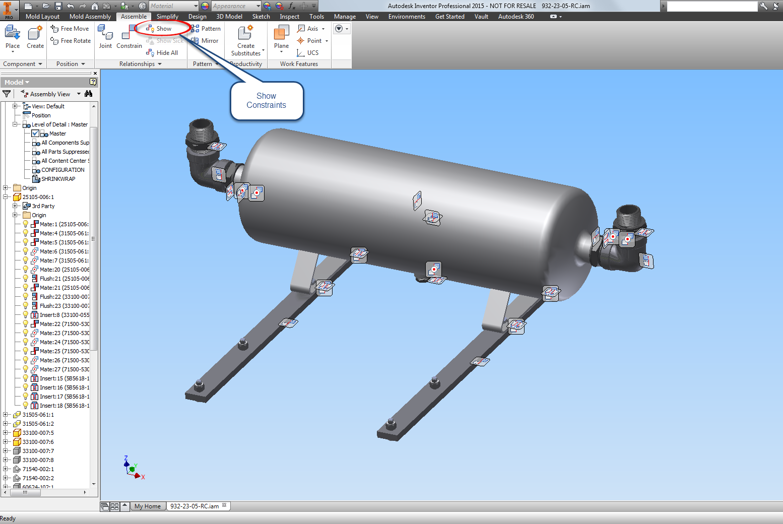
Show constraints displays the constraint glyphs for a component that you select.
 |
| Showing Constraint Glyphs |
Show Sick constraints will show constraints that have conflicts with other constraints.\
 |
| Showing Sick Constraints |
Hide All constraints turns off all the glyphs.
 |
| Hiding All Constraints |
I know I've grown to like these tools as I've used them, but it can be easy to overlook them.
So if you've been upgrading and forgot about these tools, take a look!
And I know. There isn't a video for this one. Things have kept me rolling where I haven't quite been able to create videos. I'm hoping that things might just wind down enough where I hope to create one soon!
****Edit 31-December-2014****
At long last, I had the time to create a video to accompany this post! Take a look! I hope you find it helpful!
And Happy 2015!


No comments:
Post a Comment