Find us on Google+ Inventor Tales

Friday, November 02, 2012

For a Little More Fun! - Modeling a 10 sided die!

“The dice of Zeus always fall luckily.”
Sophocles

After creating the 20 sided die in my post last week, I decided to embrace my inner geek even further and create another die of the standard gamers set.

This time I chose to create a model of the 10 sided die.

The finished 10 sided die
To add a little more fun, here's a new trick I'm trying.  Embedding a dwf of the die inside the webpage!  Try giving it a rotate and pan!


When I started to look at building this die, I found this model easier to create that the 20 sided die.  But even though I thought it was a little easier to create, I also found it had it's own set of challenges.  It took me a few tries before I got a result I was happy with.

I ended up using two lofts, and trimming the plane where they met to get the result.  I then added fillets to clean up the edges and get the result I was looking for. 

But, without further adieu, here are the steps! 

  • The first step was to create a single line on a sketch plane.  I'm going to use each end of the line as one end of two lofts I'm going to create. I also made sure that the midpoint of the line was placed at the origin.  This will let me use the origin workplanes to create sketches in my next steps.

The first line defining the top and bottom of the die.

  • Next I created a sketch on my origin plane, added a pentagon, and dimensioned it.

The additional sketch added.
  • Now I'm ready to loft between the two.  I choose the loft tool, and loft between the pentagon and one of the line's endpoints. 

Creating the loft

The finished loft

  • Before I started modeling, I looked at an image of a real die, I realized that the upper and lower halves were offset, so I couldn't use the same loft.  So I created a second pentagon, rotated from the first, and repeated the steps above.

Creating the second loft.  Notice how it's offset from the first.
  • Now I was left with sharp overhangs on the die that weren't going to work at all. It was time to clean those up!


The die before cleaning up.  Not pretty at all!
  • To clean up the sharp corners, I created a sketch where the two pentagons meet.  (Note I used slice graphics, just like in my previous post here).  I sketched a circle, then used Extrude with the intersect option remove the sharp corners.
Creating the feature for the Extrude commad


Extruding using the intersect option
  • Now the hard work is done.  All that is left is the tedious work of adding the numbers.

Adding the numbers to the die
  • And finally, using the fillet tool to round off the sharp corners!
All done!

 A quick rendering, in Autodesk Showcase, and I'm ready to go!


 Just like with the 20 sided die, below are two links where you can download the model if you'd like.  And just like before, all I ask is that you give a me a little nod if you decide to use the model.  Enjoy!

Download from Autodesk 360 

Download from GrabCAD (login required)

Wednesday, October 31, 2012

Happy Halloween! & Flipping Normals in Autodesk Showcase!

“For me, writing something in the spirit of Halloween is like Mother Teresa writing on charity and sacrifice. It's just second nature to me.”
Danny Elfman

Today's blog is just a quick blog to say "Happy Halloween", and add a quick tip for Autodesk Showcase.  . 

Earlier today I downloaded a 3D model of a skull, in a STL format, from GrabCAD and imported it into Showcase.

But once the file imported.  It looked dark.  Almost like charcoal.   It was like the environment light was having no effect on it.


This skull shouldn't look this dark.  Somethings wrong (hint: check normals)

Experience has taught me what the cause of this is.  But not everyone may know the secret. 

The normals on the skull were all reversed. 

For those who may not  be as familiar with surface normals, each surface in Showcase has a positive and negative side, often referred positive and negative normals. 

While I can't say I know all technological reasons for the how the normals behave.  I do know one thing.  If the normals are backwards, which sometimes happens on imported models, the object won't light correctly.  That's what's going on with the skull.

So now that I know what's wrong, how do I fix it?

  • First, I went to the "Appearance" pull down menu and choose "Visual Styles Library". 

Bringing up the Visual Styles Library


  • Once the Visual Styles Library menu appears, expand the "Diagnostics" section.  This is where I find the option for "Normals".  Choosing this option, I see that the entire skull shades yellow.

Viewing the Normals
  • The yellow indicates that I'm looking at the negative side of the normal. This is why the skull isn't lighting correctly.  Showcase is also helping me out by telling me to Select an object and hit the "F8" key to flip the normals.

The yellow tells me I'm looking at the negative (back) side of the normal
  • I can hit the F8 key or I can select my objects and choose Edit>Reverse Normals from the pulldown menus.

Flipping the normals
  • The normals will flip, and the skull will turn blue.  This tells me I'm looking at the positive side of the normals now. 

The normals are flipped!

  • Now, all I have to do is select a new option from the visual styles (I chose the "Both Shadows and Ambient Shadows" option)


  • Now the skull looks a whole lot better, and I'm ready to complete the rendering.  Add a few shadows and lights, and I have something I can say "Happy Halloween with!

The skull with some materials and lighting

And with glowing eyes!
So that's it, a quick tip on flipping the normals on a model!  Have a great holiday everyone!


Sunday, October 28, 2012

Using Slice Graphics & Project Geometry in Autodesk Inventor

“The best thing since sliced bread”
Proverb

The Autodesk Manufacturing Academy concluded, I've taken this weekend to recover and catch up on things put off for AMA.

So I created a simple tip this weekend, but one I think is important.

Using Slice Graphics, and Project Geometry. 

Slice Graphics is a great tool for cases where you need to create a feature inside a part, and you can't easily see inside the part's cavity. 

Slice Graphics will give a virtual slice that cuts away a portion of the part so the inside can be seen.  Bear in mind this slice is virtual, like a section view in the 3D model.  It doesn't actually cut anything away.

All that is needed is an active 2D sketch.  When the sketch is active, right click (or hit 'F7' if you like hot keys, and you can toggle slice graphics on.  Repeating these steps will also turn it off.

The right click menu that toggles slice graphics on or off.

Now with the sketch active, Project Edges and Project Cut Edges show their value.

Project Edges will take an edge that isn't on your sketch plane, and project it onto the sketch plane so it can be referenced.  This can come in real handy when you need those edges to reference.

Project Cut Edges will project all the edges that have been cut by Slice Graphics.  I think this is a great tool when working inside of a cavity, like just like the part pictured above.

These tools are found on the Sketch Tab, when a sketch is active.

The Project Geometry, and Project Cut Edges tools.  Found on the Sketch Tab

And of course, here's a quick video on how these tools work. 

One last thing, when you create a feature, try Right Clicking, and choosing "Create Feature" to create the Revolve, Extrude,etc.  It opens up the appropriate tool, without turning off Slice Graphics.  It makes picking things a little easier!


Friday, October 26, 2012

All for Fun – Creating a 20 Sided Die

Death and the dice level all distinctions.
Samuel Foote

Many years ago, I friend asked me to create multi-sided die for a website he was creating.  You can still see the images on the banner of the website for DiceHouse Games here.

It was a tricky one to create.  It was a 20 sided die, a much used tool in role playing games like Dungeons and Dragons.

An Autodesk Showcase Rendering of the 20 sided die model

I also used it as an example in a blog post for using the “Change View Orientation”  tool inside of Autodesk Inventor drawings back in February 2012.  

***Edit 13-Nov-2012 : Added an embedded dwf of the 20 sided die***


A 3D dwf of the 20 sided die

*** End Edit***
Since that time I’ve started getting requests for how I built the die, as well as a location to download the actual *.ipt file.  

So here are the steps on how I built the 20 sided die!  


1. I found the definition of a Icosahedron (a 20 sided polygon) on Wikipedia.


The construction figure that started it all!

2. I created three sketches on the XY, YZ, and XZ origin planes in Inventor


The three rectangles on each plane to create the framework

 
3. Next, I used a 3D sketch to connect the vertices together, must like in the Wikipedia image.  If you’re wondering, this did take quite a bit of time. 


The process of creating the skeleton


4. This becomes the skeleton where I create several boundary patches.  The boundary patches create the surfaces of the die using the “sketch skeleton”.    This was also pretty laborious!

Boundary patches created close surface that could be stitched.


5. I then stitched the surface.  Since it’s “watertight” (completely sealed), it becomes a solid.

Stitching the surfaces make it a solid
6. Now it I had to add all the numbers (which were extrusions), and fillet the sharp corners. That’s it, I was done!


The completed die

So in conclusion, this was a satisfying little project took a little bit of research to figure out how to construct it.  Once I figured out the process, the steps weren’t difficult, but it did take time and patience to execute. 
 
Placing the 3D wires lines took a lot of time, and more than once I had to correct a line I misplaced.  The boundary patches took less time, but putting in all the numbers was an exercise in patience too.
 

So because of the requests, I’m uploading the file to a couple of sites for download.  However, before you go grabbing the file, I make only one request.
 

I spent several hours of a Saturday figuring this out.  All I ask is if you use this model, give me a nod and a little credit for the time I put into it.  
 

Now for the download sites!
 

The first is my Autodesk 360 site: Click here for Autodesk 360 download
 

If you use the GrabCAD file sharing website, you can also log in and get it here:  Click here for GrabCAD download


Sunday, October 21, 2012

Using the Transitional Constraint in Autodesk Inventor

Life is pleasant. Death is peaceful. It's the transition that's troublesome.
Isaac Asimov

This week proves to be another busy week as my second round presenting at the Autodesk Manufacturing Academy (this time in Cerritos, Ca.) comes around. 

That's right, even though I've been through it one time, I have to review my sessions, polish, an improve them.  Not to mention making sure I don't forget anything! 

But I did find time to create a quick video on an Autodesk Inventor tool that has been around forever, but seems to have drifted into obscurity as new features and functions have appeared over years of Inventor's evolution.

That tool is the Transition constraint.

The Transition constraint being applied to a "Cam and Follower"

Looking at the image above, it might make sense to use the Tangent constraint.  It would seem perfect to hole the cam and follower together. 

However, if this constraint is used, the tangency will only follow one face.  It won't transition to another face like the follower would in the real world.

This is where the appropriately named Transition constraint comes into play.  It can "see" the faces it need to transition to, and behave appropriately.

By using the Transition constraint.  Inventor will allow the follow to "follow" the cam correctly. 

Below is a video showing the behavior with the Tangent constraint, which isn't what I want, then I'll show the behavior with the Transition constraint, where we get to give the "big ol' nod of approval"! 

Thursday, October 18, 2012

A "Guest VIdeo" on Autodesk Showcase Materials

“The only thing more expensive than education is ignorance.”
Benjamin Franklin

Every once in a while I run across a resource that really captures my interest. 

Sometimes it's some sort of low pass by an airplane with a big piston engine, other times it's something silly like the "fainting goat" video YouTube.

But yesterday I came upon two fantastic Autodesk Showcase videos created by Marion Landry from Autodesk.

Marion created two outstanding videos on creating and manipulating materials in Autodesk Showcase.

I've already watched them once, and I picked up quite a few tricks I'll use in the future.  As a matter of fact, I'll watch them again, just because I know there are more tricks I'm going to pick up.

So here are the videos that Marion has graciously created for us.  Be sure to check out her channel here!

Creating Custom Materials Part 1


Creating Custom Materials Part 2


Sunday, October 14, 2012

A "Weekend Sebatical" Learning Practical Sheet Metal

“So never lose an opportunity of urging a practical beginning, however small, for it is wonderful how often in such matters the mustard-seed germinates and roots itself.”
Florence Nightingale

This week, a video blog post gets postponed.  Why?  I took a "weekend sabbatical" and took a two day class on hand building sheet metal aircraft parts. 

Why?  Because I miss getting my hands dirty, I love learning new things, and I wanted some practical knowledge that is only learned on the bench with real

I've seen the volunteer mechanics at Planes of Fame Air Museum working their craft, and been amazed by how easy the make it look.  All the while knowing it's not nearly that easy. 

So there I was, standing over a bench, looking at a pile of unformed aluminum parts,  countersinks, riveting guns, and pneumatic drill motors, wondering how I was going to "use those to turn that into something that looked like a simple aircraft structure".
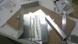

My completed "practice project" is at the top.  I'm supposed to turn the pile of metal into something resembling a wing structure!
 I look around a second, and wonder if this is a good idea after all.  If I run now, no one will ever know.  I think for a second.

The first day I spent on a "practice part".  Just getting the hang of center-punching, drilling countersinking, and riveting.

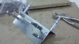
This was my "practice" project.  All I did here was get used to the tools. It's partially completed here.

The first real life lesson I learned.  There's skill that goes into this.

Not that I thought it was a simple task before I tried it.  I knew it took skill, but it takes a lot of skill. All those mechanics I saw who made it look easy, are more than mechanics or technicians.  They're masters of their craft.

So how did that practice project go?
  • I got my holes drilled more or less in a straight line.  (Even center-punched, the drill walked a bit),
  • The countersinks came out good (redemption!)
  • The rivets were more or less correct.  (I need to be more diligent about preparation)
I did learn that it's no big deal to center-punch and drill out a rivet though! 

The next day, I had to actually make a basic wing box.  I learned how to use a wooden form the ribs from flat sheet.

Then it was more drilling, deburring, countersinking, and riveting.

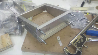
Beginning the wing box.  Cleco pins temporarily hold it together
 And when I say a lot, I mean a lot!

I bucked flat rivets, universal (domed) rivets, I pulled pop rivets.

I drilled, bucked and drilled some more.

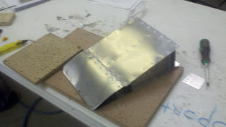
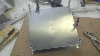
The partially assembly wing box with the top skin being attached.
 I learned a lot about how things like this are done.  I learned even more about how not to do it!

So in taking the time to do this project what did I learn that I can apply back to my "Computer Aided Design World"?

  • For every step I thought I knew about the process, there's some someone who has been around for twenty-some-odd years who knows all the steps I never heard of.
  • The term "sweat equity" is something executives use to describe hard work.  It's equivalent on the shop floor is "blood, sweat, and tears".  Building something with my own hands made me appreciate the value of the latter term.  The latter term is far more literal.
  • Speaking of  blood.  When a craftsman of this trade cuts himself, he'll clean the part before getting a Band-Aid, because he knows "blood is corrosive". 
  • Yes, I cut myself on the edge of an aluminum panel.  This doesn't really hurt, but bleeds quiet a bit. 
  • I also pinched my finger in a Cleco clamp.  This bleeds a lot less than the cut.  But hurts orders of magnitudes more. 
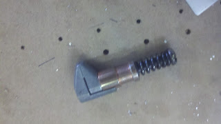
Note:  Close one of these on your finger, and it will hurt... a lot!
So in summary, it was a great experience for me.  If anything, I now know what it takes, and what I'd have to learn to be half the craftsman that those mechanics are.

This weekend gave me a new perspective on what it takes to build those designs that come so easily in the computer, and that it would be wise for me to never take that craftsman level of skill for granted.

So I guess the final question?  Will I continue, after spending an entire weekend building something that was mediocre at best and busting my knuckles (literally), would I take something like this on again?

Absolutely.  And why would I tackle this again?

Because however many mistakes I made, and however ugly that first part came out. 

I know I can do better, and I know I can learn more.  

And I learned to appreciate the craftsman that make it look so easy.


The completed project.  This is the "good" side.  Don't even look at the other!


Thursday, October 11, 2012

Outside the Box with Autodesk Inventor Publisher and Techsmith Camtasia Studio

“Hindsight explains the injury that foresight would have prevented”
~Unknown

For the second time, I've taken a video exported from Autodesk Inventor Publisher, and created a set of narrative instructions by editing the video in Camtasia Studio by Techsmith.

In this case, I created it as a sample for KETIV's Autodesk Manufacturing Academy in Oregon, which was yesterday, October 10th, 2012,  and California, coming up on October 25th, 2012.

Just like before, I started with an assembly.  This was a Dual Throttle Assembly provided by Datum3 Studios

The Dual Throttle Assembly created by Datum3

But just like any "2.0" version, this one is improved.  Sure, I had better tools in the sense that I had more current versions of both softwares (Inventor Publisher 2013 & Camtasia Studio 8.0), but I also have gotten better at creating them as well.
 
But putting aside the "fun and excitement" portion of the task, I realized there was a "real world" lesson hidden in my fun and games.

First, think outside the box.  I know I can be guilty of thinking about using my set of CAD tools to solve all my engineering and design problems.  Sometimes I fail to ;ook beyond what I can do with a little bit of creativity.

In this example, I wanted to use a voice-over.  Perhaps text or video instructions alone just won't cut it.  Perhaps this is going to be a file for use overseas.  With the help of a translator, a voice over could be created in several different languages for several different locales.


Not to mention the fact that I got to edit the video exported out of Inventor Publisher, edit it, and throw some cool transitions and effects.

That's where I took the video file from Inventor Publisher, imported it into Camtasia Studio, and started the editing process.  I threw in transitions, intro and outro slides, as well as watermarks, and credits!  

And as part of that "credit where credit is due" process, I can't thank Datum3 Studios for the use of their Dual Throttle Assembly..  This project would have been a lot tougher without their help!

Check the Dual Throttle assembly, and some of their other cool work, on their projects gallery here! 

So here's the result of a some spit and polish, and a few virtual blood, sweat, and tears.  I hope you enjoy, and maybe get a little inspired by a project I had a lot of fun creating.


AMA Oregon was great, by the way.  I only had time to take a few pictures off my smart phone, but here's a little of what went on!

KETIV's John Aiello presents to the crowd

Janna Spicer explains the benefits of the First Robotics Program

And everyone had a chance to mingle!


Sunday, October 07, 2012

Crunch Time Previews! - Linking between Autodesk Inventor and Autodesk Showcase

“My body felt extremely tired, ... I've got five or six gears in me, but I was crunching to get into second without a clutch. It was a tough day.”
Grant Hackett

Today is a much shorter post that usual, since most of my waking hours has been spent on creating my materials for KETIV's Autodesk Manufacturing Academy in Oregon on October 10th. 

So in this post, I'm afraid I don't have much that I can get into regarding new adventures or experiences, since..... well.  Look at that above statement on AMA!

But to that end, I've got a fantastic dataset graciously provided by Datum3 Studios.  You can check it out as the "Flight Controller Bases" section in the gallery HERE!  This data will be playing a big part in my "Digital User Manuals & Documentation" session.

The Throttle rendered in Autodesk Showcase
As part of the event, I've been busy creating supplemental videos that go along with the sessions, so this is what I'm sharing today.

In this video for AMA, I briefly show how Autodesk Inventor and Autodesk Showcase can link their data together, creating a loop of "collaborative development" where the rendering in Showcase can develop along side the engineering design developing in Inventor.

By utilizing this process, the aesthetics of a product can be developed and approved by the customer, all the while the engineering is going on in the background.  Both can develop simultaneously, instead of linearly as in the "traditional way".

Here's the video!  I hope you all enjoy this AMA preview!


Sunday, September 30, 2012

Using Model Sketches on a Drawing in Autodesk Inventor

“You can't do sketches enough. Sketch everything and keep your curiosity fresh.”
John Singer Sargent

Last week, I was talking to someone about how to best represent a spot weld in Autodesk Inventor.

The first observation to make is that Inventor has a Weldment environment that provides several tools to help with welding.  It's got a variety of tools.  It can separate the weldment into different sections, the assembled environment, the preparation environment, the welded environment, and finally machined environment.

This is a great tool if a high degree of detail is needed in creating a welded environment.

But what if  just a simple representation is needed?

In the brainstorming session, an idea was brought up.

What about creating a sketch in the assembly, showing the spot welds in the sketch, then showing it on the drawing?

The sketch added to the model

The sketch added to the drawing


I tried it.  It works!  The sketch can be shown, annotations can be added and so on. 

Here are the basic steps:
  1. Create a sketch on the model (part or assembly)
  2. Place the view in a drawing.
  3. Right Click the Assembly in the Drawing Browser
  4. Choose "Get Model Sketches"

And BOOM!  That's it.  It's pretty easy!

So keep this in mind for your designs.  And keep it in mind for any application it can help in.  I used spot welds in this example, but any place a sketch can help, use it! 

Of course, here's a video showing the example I described!


One last thing.  Do you have a place where this workflow helped you out?  Share a comment and let me know!

Sunday, September 23, 2012

An Autodesk Manufacturing Academy Preview video - iParts

“The whole is more than the sum of its parts.”
Aristotle

It's been another busy weekend.  I was busy catching up with family, so I'm afraid no blog was built today. 

However, I have been busy putting a lot of work into KETIV's Autodesk Manufacturing Academy, so as this weeks post, I offer up a preview video for my "Automating Repetitive Designs" session.

This particular video is on the iPart portion of the session

Recall that an iPart is a "table driven part" where a component of shape can be controlled, via parameters.  This makes it much easier to create different sizes, colors, and so on, without recreating the part every time.  The table helps drive that geometry.

A classic example of an iPart, open up the McMaster Carr catalog, and look at any screw you can find.  See that table of values?  iPart!  

So without further delay, here's a video.  Enjoy!

I hope you enjoy, and I hope to see a few of you a the AMA event!

I'll see you in next week's post! 


Friday, September 21, 2012

Off Topic - The Space Shuttle Endeavour

“What is history? An echo of the past in the future; a reflex from the future on the past”
Victor Hugo

It can definitely be said that this post is off topic.  I didn't use Autodesk Inventor, Autodesk Showcase, or anything for this blog.

All I had was the opportunity to see the Space Shuttle Endeavour make her last flight to her final home, The California Science Center.

I couldn't resist.  This would be the last time that I could see a space shuttle in the air, even if it was riding piggy back on a Boeing 747.

A few of us from the office headed a few miles down the road to Anaheim, and saw the 747 carrying Endeavour on it's fly by of Disneyland.

It was impressive on so many levels.  The engineering feat of the 747 carrying Endeavour, the excitement being able to watch history being written. 

And last but not least, a little bit of sadness knowing that this is the end of an era.

So hear are my pictures of "Endeavour's Last Ride".  I hope you enjoy them as much as I did! 

At first it looked like a ghost in the Southern California haze.
But it was very real indeed!

You could feel the excitement in the air.

It was amazing to see it get closer.

And just keep getting bigger.

And bigger!

And become a truly impressive sight!

The chase planes look tiny!

A grand entrance for Endeavour

And she heads away

Her flyby is over.

And a grand space craft heads for her final home.


Wednesday, September 19, 2012

Backing Up Autodesk Vault - On a Budget

“Back up my hard drive? How do I put it in reverse?”

I would be the first to say that we should all be making backups of our CAD data!

Do you think I follow my own advice?

Pffft!  No! 

Of course I have my excuses!
  1. My CAD Data isn't use for production, so it's not critical.
  2. I work in a highly mobile environment, and everything runs on my laptop.   That means I 'm not connected to a good backup server much of the time
  3. I'm too lazy to take 15 minutes to plug in my portable hard drive and copy my Vault Backup over to the drive. 
  4. The most famous, used by many; (wait for it). "It hasn't failed yet!"
Are these good excuses? 

Pffft! No!  

So if  the The Oatmeal's Famous "Tumbeasts" made an appearance and at my hard drive, I was out of luck.


Try passing this excuse off at work.


One day, I had an epiphany that was worthy of MacGyver.

I implemented it, and thus far it's been working well! 

First I had to take stock of my assets.
  • I already have a script that backs up my Autodesk Vault database and filestore that contains my CAD data. 
  • I have a Dropbox account that has more than enough room to accommodate my current backup
  • At my home, I have an old retired computer that I use as a data server, which also has plenty of room for my Vault database and filestore.
That's enough for me!

I created a new script that moves my backup file to a Dropbox folder.  In turn, that folder syncs up with my online Dropbox account, which is stored in the cloud.

My Vault Backup in my Dropbox Folder


BOOM!  Backup! 

Then, I setup my old data server to sync with my Dropbox account, so now I have a backup at home, as well as on online! 

BOOM!  Redundancy!  

I've been running this system for about a week now, and it's been working pretty well.  I've restored from it once already successfully

But just like everything it's got good and bad. 

First the good!
  • It's a simple and effective backup strategy, especially for the budget minded. 
  • By using Dropbox, I can sync the backup to multiple machines, they just have to be syncing to the Dropbox account.
Now the not so good!
  • Since this is a cloud backup, there needs to be sufficient bandwidth to support uploading and downloading potentially gigabytes of data.
  • Online storage accounts, such as Dropbox, Autodesk 360, and SkyDrive have limited storage capacity (typically a few gigabytes until you purchase more).  So monitoring usage can be important, especially as data gets larger.
Fortunately, my Vault data is about 750MB, so I have more than enough room in my Dropbox account (over 6GB), and I upload across a fiber optic line, so bandwidth isn't an issue for me, so this is effective for me.

In summary, this system probably isn't good for everybody, but for a small environment, with limited resources to purchase hardware and infrastructure, it may be exactly the ticket.

P.S.  I'm sure there are those of you might be wondering why I didn't use my Autodesk 360 account.  The reasons are simple.  I tried my Dropbox account first, and I'm too busy (read too lazy) to switch it over.  I could just as easily have used my Autodesk 360 account!

I hope this is a tip you might be able to use in your own environment!

Have another idea to create a backup like this on a budget, check out the comment section! 

Sunday, September 16, 2012

Using an iFeature in Autodesk Inventor - Part 3


“All respect comes from persisting to completion.”
Melissa Lima

At long last!  The final part of my little "iFeatures & Autodesk Inventor" series (at least for now)!

In this final post, I'll discuss taking and iFeature, and driving it via a table.

But first of all, why drive an iFeature with a table?  What does a table do for us?

Well the single biggest reason to use a table driven iFeature is to create is to create a consistent series of choices for features that vary in predictable ways.

An Example of an iFeature Table
For example, lets say there's a mounting hole of three consistent variations.  It may have two different size holes, but the holes all expand in intervals of a given increment (.125 inches for example).

An example of different holes (yes, I know the biggest one is 'too big'
If  a non-table driven iFeature is used, the different diameter holes could be mixed and matched.

The 'standard' iFeature screen
In other words, a "create a combo" situation could arise, and a non-existant hole created.

If a table driven iFeature is used, then the mounting holes can be called out by a specific value, such as an "tool number", and a consistent set of holes can be placed.

Special fields can also be created, so institution specific criteria can be used for selecting an iFeature.  For example, in my video, I use Tool Number.

But enough of the describing! Let's switch to the video, and see how these tables can be used!


And on a final note.... Who knows what an iFeature was called before it was named an iFeature? Hint: it's the reason an iFeature has the file extention "*.ide"!