Find us on Google+ Inventor Tales

Monday, November 03, 2014

How Precise is Precise? Changing Measure Precision in Autodesk Inventor

“Most of the most important experiences that truly educate cannot be arranged ahead of time with any precision.”
Harold Taylor

KETIV's AMA 2014 in Southern California is a wrap!  It was good to see everyone, and as much stress as it was preparing for the session I helped in, it was fun presenting again.

But out of that course came one question that I didn't know the answer to.

"How can you change the default measuring precision in Autodesk Inventor?"


The default measure location behavior
At the time, standing in front of the room, I didn't know the answer.  After all, I don't know everything!

But over the weekend, the thought would occasionally return to me.  I felt like there might be a way.

Finally, I had a little bit of inspiration, and decided to give it a try.

Opening up Inventor, I played a little bit of a hunch.  On the Tools tab, I located Document Settings and opened up the Document Settings dialog.

Using Document Settings


Once on the Document Settings dialog,choose the number of decimal places you want by changing the Linear Dim Display Precision (or angular if that's your preference).

Changing precision

Once that's done, the measure precision will change for this document.

Precision reset. 

But wait, I said default setting, right?   If you want to make this a default behavior, the final step would be save these settings into a template file.

One way would be to open the templates from their location, make the very same change, and save that file.  This would change the existing templates.

The other would be to start a new file, make any changes you want, and choose the Save Copy As Template option.


Save as a Template

Whichever you choose is up to you!

On a final note.  I know that there are those who might want a different functionality.  And that's okay!   Share your ideas on the Autodesk Inventor Ideastation!

Sunday, October 26, 2014

Scroll Wheels in Autodesk Inventor and AutoCAD. They can behave the same!


As the Autodesk Manufacturing Academy (AMA) gets closer, I find myself pretty busy.  But I still wanted to share a tip, even if it's short.

Here's a simple tip that sometimes comes up when I'm training my Inventor Essentials class.  It's most often encountered with users who have to constantly switch between Inventor and AutoCAD. 

"Can scrolling in Inventor and the scrolling in AutoCAD made to match?"  

That's right, by default, Inventor and AutoCAD don't scroll in the same direction.  I've been told that's because one program views the geometry as moving toward the camera (or user), the other one views the camera (or user) moving toward the geometry. 

I don't know if this is true or not.  But it at least sounds good. 

More importantly, there's a way to make them work the way an individual user (that means you!) can make each program match. 

First, in AutoCAD, type ZOOMWHEEL.   

Change the setting to 1 or 0.  Use whichever suits your preference. 

Type ZOOMWHEEL in AutoCAD

Now, in Inventor, go to Tools>Application Options>Display

Locate Zoom Behavior, and set that to the preference you like. 

Changing zoom behavior in Inventor

Everyone is a little different, but between these two variables, you can get them to do what you want, and get them to be consistent about it! 

In the meantime, I'm back to getting ready for AMA! 

Monday, October 20, 2014

Just for Fun, and Some Weary Humor Coming Out

I've still been in a loop of training, getting ready for training, and preparing for KETIV's AMA event on October 29th.

Like many people, I cringe at an overused buzzword.  I really cringe when I hear myself saying them.
So on a break, took some common buzzwords from the link here and created Star Wars equivalents of them.

Once again, Vader wins manager of the year.
Why?  Why not?  I just needed to have a little fun I suppose!

In any case, on a random whim, I decided to share them.  There's no "Inventorness" here today.  So feel free to keep moving.  Or, take a couple of minutes and enjoy my slightly warped humor.

Perhaps if enough of us start using them, we'll create a 'paradigm shift'!

  1. "Reach out" - "Force choke". 
  2. "Take off line" -"After we exit hyperspace
  3. "Shift our goal posts" - "Redeploy our stormtroopers."
  4. "Socialize documents" - "Set a course for Mos Eisley
  5. "Monetize" - "Make like Boba Fett."
  6. "Downsize" - "Feed to Sarlacc"
  7. "All in effort" - "Send the Death Star"
  8. "Accelerate" - "Jump to hyperspace"
  9. "Thought Leadership" - "Jedi mind tricks
  10. "Button up" - "Encase in Carbonite"
Like I said.  This is just for a little fun before I put my head back down and start working again.  Hope you enjoyed it, and I'm working on some more "real" blog posts soon. 

Do you have a few, feel free to add a comment! 

Thursday, October 09, 2014

Autodesk Inventor in Real Life - Tolar Manufacturing

“One man's "magic" is another man's engineering. "Supernatural" is a null word.”
 Robert A. Heinlein

This month is KETIV's Autodesk Manufacturing Academy event in Cerritos, Ca, and surprise, I've been pretty busy.

I have a couple of posts in the queue, but I just haven't quite had the chance to wrap them up.  But I work on them for a few moments when I can, so I hope to have them soon.

To tide everyone over a bit, I wanted to share a video from Tolar Manufacturing.  They've been using Autodesk Inventor for some time now to create their transit shelters, and I've been fortunate enough to work with them.

Look for the "Inventor cameo" in the video!  It's a great example of how computer aided design software touches our daily lives, often without us knowing it!

Wednesday, September 24, 2014

Lessons from the Real World. Bending Sheet Metal the Old Way

Remember, Jonathan.  Everybody knows something you don't. 
Tony the "Phantom Phixer" and one of my valued mentors

I just completed another 4 week stretch taking Aircraft Maintenance at Mount San Antonio College, and find myself reflecting on what I've learned.  What an experience!  The engineer in me enjoys getting my hands dirty again, and this time it meant driving rivets and bending a little metal (not always on purpose)

One project in my class involved creating a sample of an aircraft former.  A curved piece of structure that forms the framework of an aircraft.

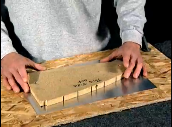
It meant going through the process of tracing a template


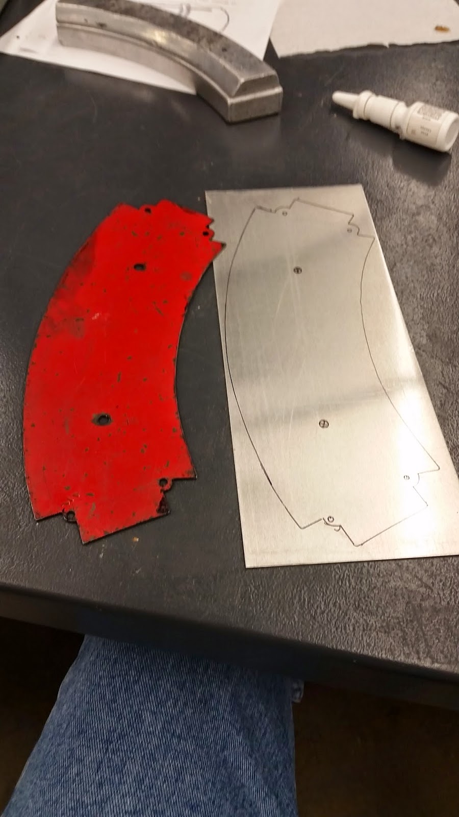
Template and blank.  Note the aluminum form block in the background
Here's a video (courtesy of the Experimental Aircraft Association) showing steps similar to what I did.  Note we had the red template with the proper dimensions, and didn't need the "magic washer".

I wasn't able to embed any of the videos.  So click here to follow a link!


After that I cut the template using Tin Snips out of 2024-0 aluminum.  2024-0 is soft, and very easy to form, but not very strong.


Tin snips. Yep, they're big scissors for metal.
Here's another video from EAA showing how tin snips are used.

To see the video click here.


I cut the part a little oversize.  Then I formed the blank over an aluminum form block using a shaped block of wood and a soft hammer.

The partially formed block of metal


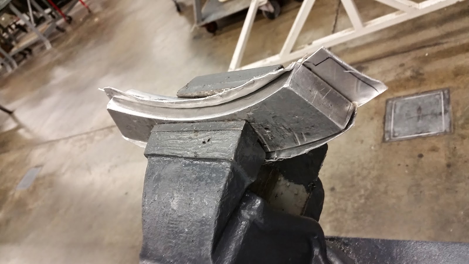
Same part, different angle.
Below, is a video of using a form block.  The video doesn't use a wood block like I did.  I also didn't use the "fluting" process they talk about at the end of the video.  I was taught to cut the material long, and by the right use of "body english & profanity" the wrinkles could be pushed into the scrap section, and trimmed away.

To see the video, click here. 


After the part was formed, I had a lot of excess material.  I cleaned this up using a belt sander, finishing it with a hand file to get the edges as clean as possible.

Granted, the edges weren't perfect.  But it was my first time, and I definitely learned what to do better the next time!


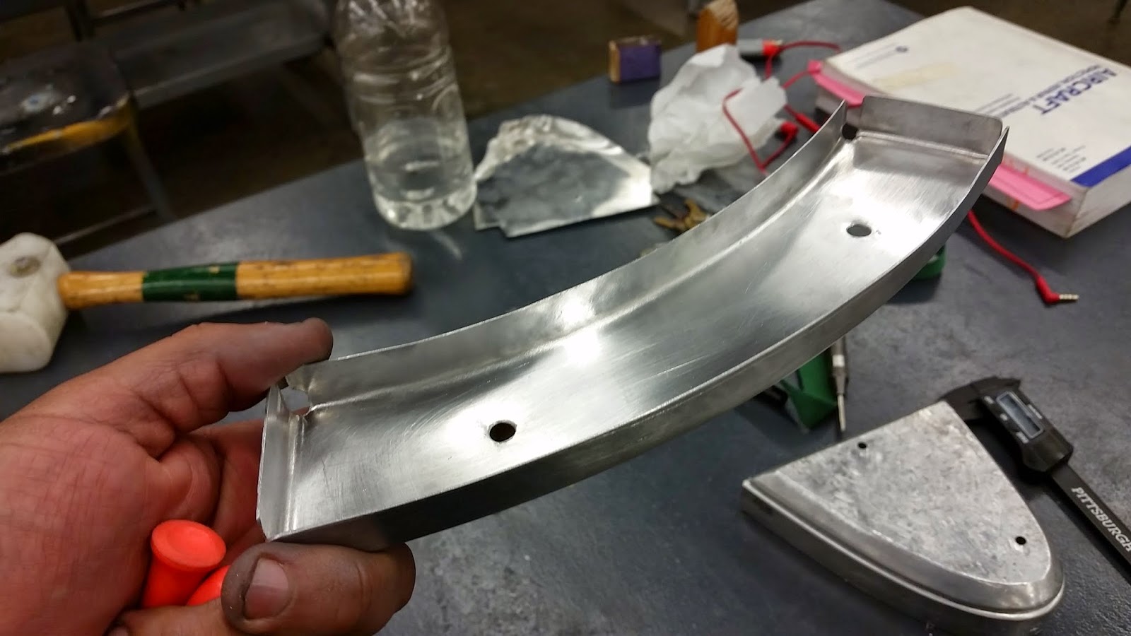
The part finished and trimmed.
Notice the soft hammer in the background,
along with the book o' standards AC43.13


Ultimately, the part would be heat treated to a T-3 temper, ensuring that it would take the loads that it it would see in a real aviation application.  Since I was just a simple student, we didn't go through this step.

The lessons I learned doing this were immensely valuable.  I just can't dismiss them.

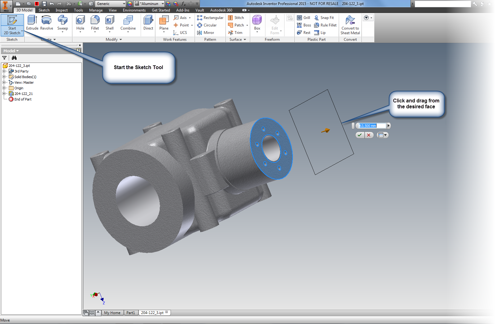
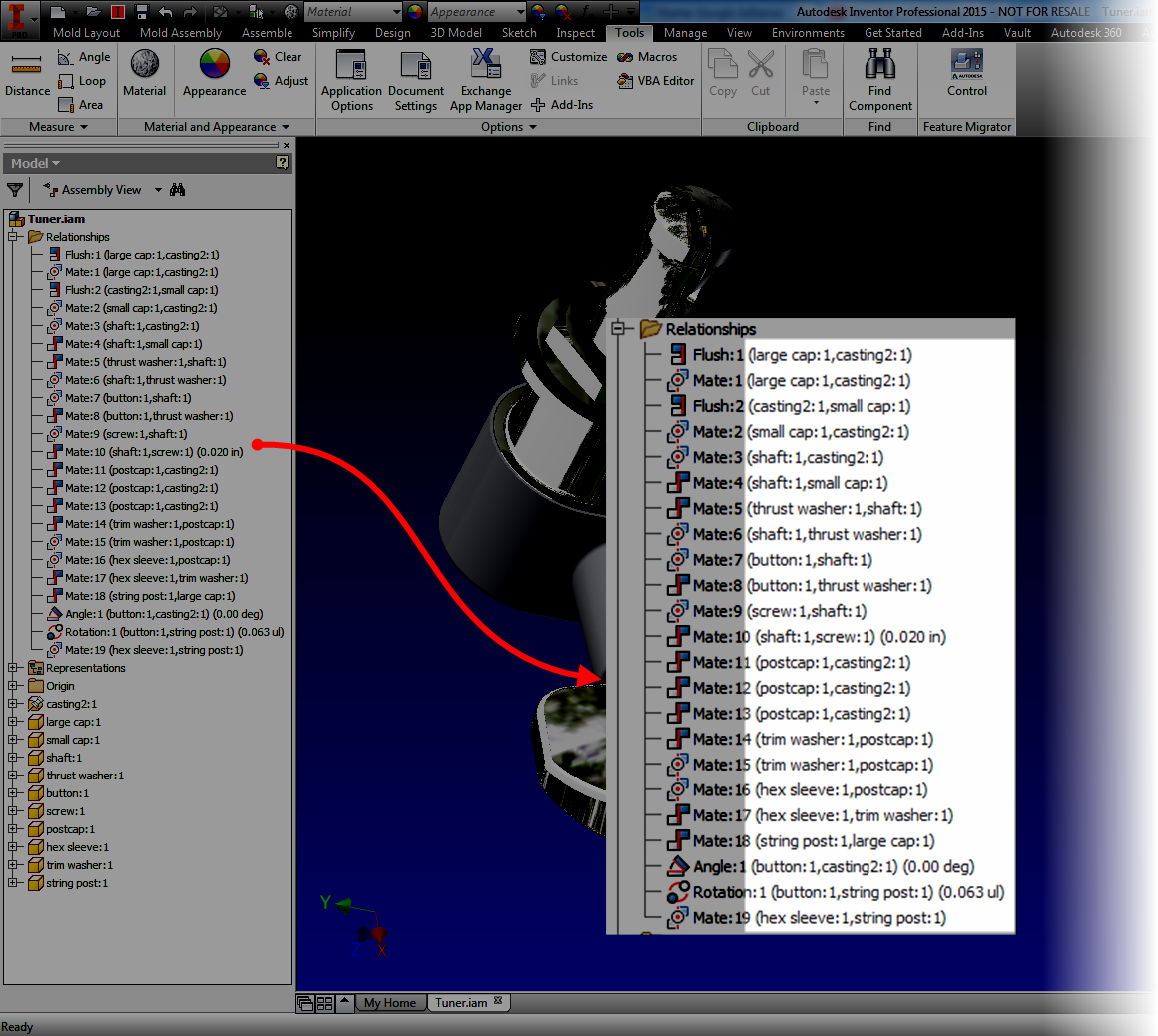
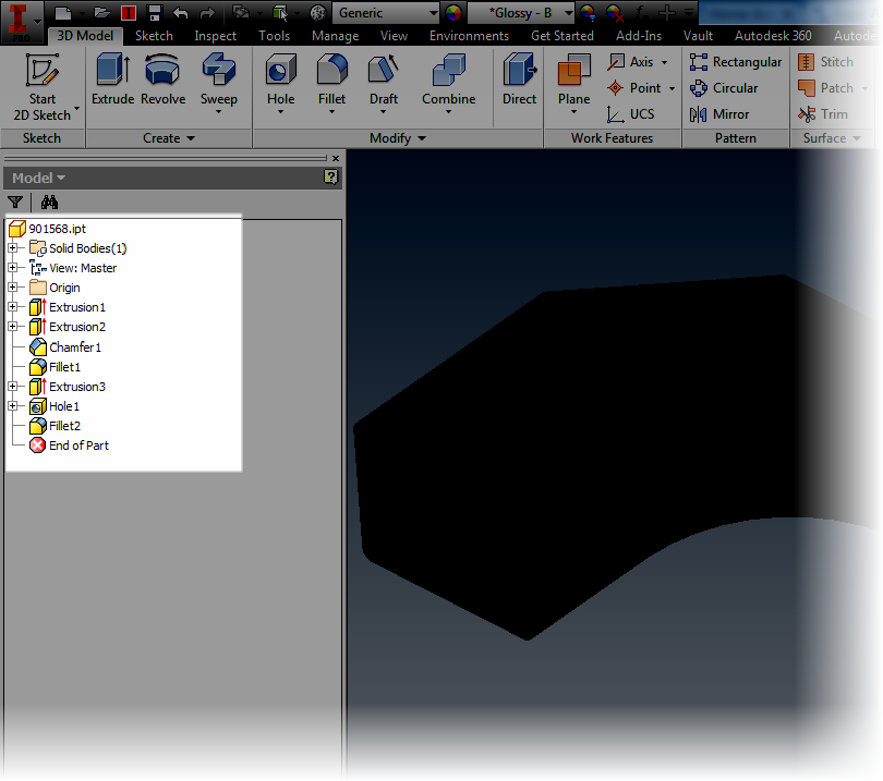
The first thing I did was contrast it with my 3D CAD experience.  I have tools at my disposal that could have designed the part in 3D, and created the documentation, and so on.

So why in the name of the "Wide Wide World of Sports" would I not use them?

Why use snips, a form block, hammer, and a bucket full of patience to build the part?

The answer, in the end, was affirming, at least to me.

The right tool for the right job.  Just because you can use a power sander, that doesn't mean that you'll never hand sand again.  Sometimes there is such a thing as "too much power".

Granted, my part was just a sample, a training session doing something that represents a typical process.  But I've seen the "real mechanics" creating parts to repair a 60 year old airplane.

In those days, there was no "Computer Aided Design" software.  A "cad" was a rather improper or rude man. The mechanics are matching reality without the benefit of a virtual world

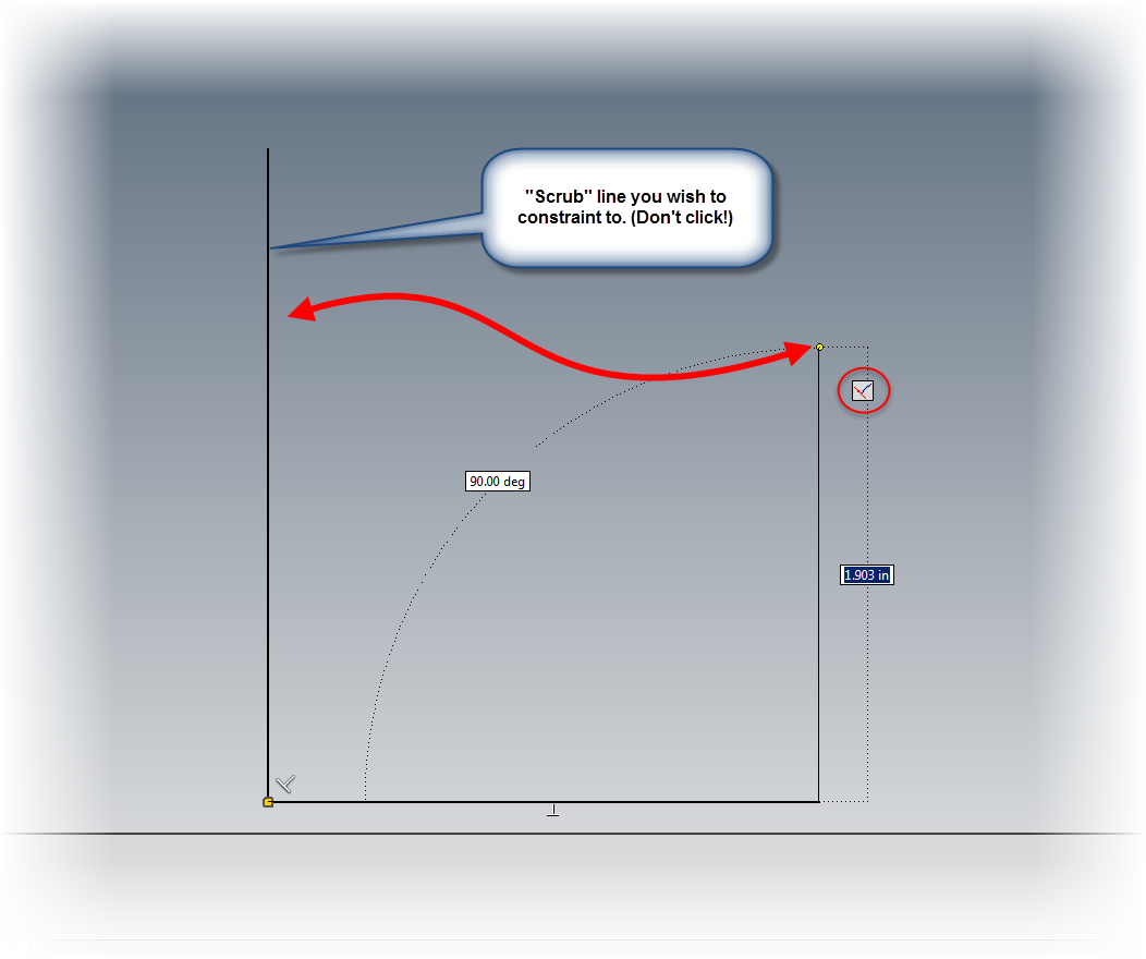
Still, why not "whip out some Inventor and generate the flat pattern for that bad boy?   Trust me, that would be awesome.  I would love to do that!

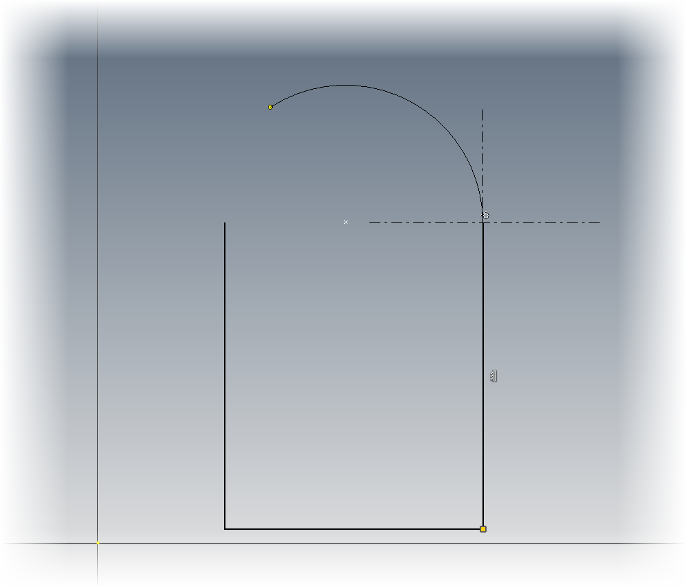
But it would still take time to generate the part, ensure my unfolding rules are accurate, and then go about making the part.

And that would still leave me with having to make a form block, and form the part.

Right tool.  Right job.  And don't forget, right process.

It's just as, if not more, effective to make a form block that fits where the finished part is going to live.  Then form it, trim it, and heat treat it when all is done.

Thought provoking, isn't it?

What's the moral of the story?  Maybe there isn't one.  Maybe I'm just rambling.

But what I learned is that no matter what I'm doing, it pays to know all the tools and process I have at my disposal, and find the best tool for the job.

Sometimes, that means dispensing with fancy technology, reaching back in time, and going back to the old ways.


Monday, September 15, 2014

Five Quick Tips for Autodesk Inventor Part modeling


“He's been a part of the whole run.”
 Gary McNamara

My last post, I talked about 5 tips that could be used in Autodesk Inventor Sketching.  Now, I've decided to go ahead and share a few tips in Autodesk Inventor part modeling that everyone may be aware of.

They're quick, they're simple, and they work for me.  I hope that the 'Verse out there can find a use for them too!

Just like before, the order doesn't imply a preference, just the order the popped into my head.

1. Create an offset workplane at the same time a sketch is created.  

It's a pretty common practice to create an offset workplane, then to follow that up with a sketch.  An example would be creating a boss that's being attached to a cylinder.

But did you know that you can create both the plane, and the sketch at the same time?  Here's how!

Start the sketch tool in which ever way you prefer.  Then much like you would create the offset workplane, drag the sketch.  The workplane and sketch will be created at the same time!


Dragging the sketch and workplane at the same time. 

The one sketch, one offset plane, one motion! 

2. Select Other

I don't think this tool gets the credit it deserves.

In brief, if there are selectable objects stacked on top of each other, the select other tool will help you pick through the part, and select additional entities, even if they're not visible.  For example. the Select Other tool will let you pick the back face of a part.

One way of accessing the tool is to hover for 2 seconds over the desired selections.  The other is to right click over the desired selections and choose the tool from the right click menu.

The Select Other tool in action
PRO TIP!  The default "hover time" for the select other tool can be changed by going to Tools>Application Options.  The setting is located on the General Tab.

Changing the time it takes for the select other tool to appear


3. Sweep along an edge.

This function has been around for a few releases.  And that's the ability to use the Sweep tool along an edge. Once upon a time in Inventor, a second sketch was required to generate a swept path. Many may still be using it the way "it used to work" still do that.  However, it is possible to just use an existing edge instead of creating a whole new sketch.

Sweeping using an edge.  The edge is highlighted, but not selected yet. 


4. Create a four hole pattern using a sketch

Inventor has been able to create holes using sketches since I started in Release 4.  As a matter a fact, at one point it was the only way to do it.  And while it could be considered an older tool, it's still a very useful tool.

One place it can be used very effectively is to create a four hole pattern, such as mounting holes in a lid.

I like using this, instead of a pattern for one big reason.  I don't like doing math with the four hole pattern.  Call me lazy.  Using the offset tool allows the sketch to be offset with one dimension, and the offset will be maintained should the overall dimensions change.

In order to do this, create a sketch and offset it's perimeter using the offset tool.  Next, just finish the sketch, and start the hole tool.  All that's left to do is place a hole on each corner of the offset rectangle using the From Sketch option.  Choose the hole type and go!

Using an offset sketch to create a four hole pattern
5. Slice Graphics and Project Geometry.

This is two tips combined in one, but they often work in conjunction.  That's why I'm combining them.

These tools are most often used when a feature needs to be created on the interior of a part, such as an O-ring groove inside a part.  Slice Graphics will virtually "cut" the part, while project geometry will project the edges cut by Slice Graphics so they can be used in the sketch.

To use Slice Graphics, start the sketch on the plane intersecting the part, and choose Slice Graphics (or hit the hotkey F7).

Once Slice Graphics is enabled, the model will be sliced at the sketch plane.  This is a virtual slice, like an XRay or MRI.  No material has actually been removed.

Next, click the Project Cut Geometry tool (it's on the flyout under Project Geometry), and select the model.  The edges of the virtual cut will be projected onto the sketch. Now that sketch can be used to create the geometry used to create the feature.

Slice graphics and project geometry already selected.  The icons are highlighted. 


So there are a few tips you can use when creating parts in Autodesk Inventor parts.  I hope that they're something you can start using right away.

******************Edit 23-September-2014 Added Video (Finally!)************************

At long last the promised video!  Take a look to see these tips in a video format!


Wednesday, August 27, 2014

Five Quick Tips for Autodesk Inventor Sketches

“You can't do sketches enough. Sketch everything and keep your curiosity fresh.”
 John Singer Sargent

A few weeks ago, I found myself training an Autodesk Inventor course.  As with any class, I always try to throw in a few of the "simple" tips.  They're the little things, but things that can be used every day, in just about every Inventor session that lasts more than a few minutes.

So as I thought about this post, I thought I'd collect a few of the common tips for different aspects of Inventor.  And what better place to start, then at the beginning of nearly every Inventor part.

Why not start with sketches?

I won't get wordy on this one.  It's time to just go ahead and jump right in.  Here are five Inventor sketching tip. The order is random.  It's not a ranking.  It's just five tips that I like to use.

So here goes!

1. Temporarily turn off automatic constraints

Inventor will try to add constraints as you sketch, such has horizontal, vertical,  perpendicular, and parallel.  But sometimes, those constraints aren't wanted.

To turn off that functionality, hold down the Ctrl key.  Automatic constraints are turned off as long as the Ctrl key is held down!

That's my high mileage, very dirty Control key.

2. Change what geometry Inventor is automatically creating constraints between

When sketching, Inventor automatically creates constraints between the geometry being created, and existing geometry.  At times this can seem to be arbitrary.  But did you know that if you "scrub" the desired piece of geometry with your cursor, you can change what geometry Inventor is constraining to.  Just remember to rub the geometry with the mouse cursor, don't click!

First scrub the desired geometry

And enjoy the result! 


3. Creating an arc while still using the line tool.

I compare this Inventor function as being similar to AutoCAD's polyline function, which is creating an arc while still using the line command. This tool takes a certain "feel" and a dash of patience, but I think it's worth it.

When still in the line tool, click on the end of the line where the starting point of the arc is desired.  Now hold the mouse button down, and imagine your drawing the arc with your mouse cursor.  An arc will appear!

Creating a drag arc


As long as the mouse button is held down, the arc can be changed.  Dragging perpendicular to the line creates a perpendicular line, dragging in a tangent direction creates a tangent line.  Lifting the mouse places the arc.

Give it a try.  It may take a bit to get used to, but it's worth it!

4. Closing a sketch with a right click.

Another command that heralds back to AutoCAD's polyline functionality!  When ready to close out a loop of sketch geometry, right click.  In the right click menu, there's an option to Close.  Save a few clicks by letting Inventor close the sketch!

Close a loop of geometry


5. Restart a line without restarting the command!

There may be times when a continuous sketch may not be needed.  But that doesn't mean that the line command has to be completely exited and started over.  To create a line starting in a different location, right click, and choose Restart.  The line can be started elsewhere without restarting the command!

Restart without exiting the command
And to go with the tips above, here's a sketch tip to see those tips in action!

Friday, August 15, 2014

Help! My Autodesk Vault Icons Are Having an Monochromatic Attack!

“Simple solutions seldom are. It takes a very unusual mind to undertake analysis of the obvious.”
 Alfred North Whitehead

I know I sound like a broken record, but still, I manage to remain busy, so creating videos has been forced to the back burner.  I am hoping to change that soon!

However, I'm still going to try keeping up with some simple tips.  And here is another one for those of us using Vault.  I ran into it just today.

I fire up my trusty seat of Autodesk Inventor, and go to grab a file from Autodesk Vault using the "Open from Vault" option.  And what do I see?

Nearly all my icons are grayed out!  I can log out, and log back in, but trying that doesn't do a thing!

Wait?  What?  Noooooo! 

What causes this?  Why would my Vault suddenly prevent me from getting to my files?

The solution is often, fairly simple.  Many times, and when I say many, I mean nearly every time, it's that the project in use isn't a Vault Project.

First, close all files.  Strictly speaking, this isn't necessary, but this will save you a step or two as we journey down this particular path.

Once all files are closed, go to the Get Started tab inside of Inventor, and choose Projects.

Time to pull the cover off. 
This step opens the project screen.  Check the active project. This is the one with the check mark by it.  Look in the lower pain, and see if it says "Vault" or "Single User".

If it says "Single User", you've found your smoking gun.


The project setting of "Single User" tells Inventor that Vault isn't being used by this project.  As a result, Inventor turns off the Vault mapping and tools relating to Check In and Check Out while this project is active.

Okay.  Now that the problem is known, how is it fixed?

There's two ways, and the solution depends on what's gone wrong.

Fix 1:  If this project is indeed the Vault project.  Right click on the "Single User" setting and choose "Vault".  If the project is checked into Vault, it's going to have to be checked out.


Switching the project


Fix 2: This is probably the most common cause that I've seen.  Make sure that the project hasn't been accidentally switched to a "Single User" project.  For example, if you've recently migrated to a newer Inventor version, the project may be switched to "Default", which is by nature, a "Single User" project.

If this is the case, double click on the correct project to activate it.  If you don't see it in the Project Editor screen, you may have to browse to it in your Vault working folder.
Resetting the project.

Believe it or not, that's it.  It can really be that simple.  But I have seen it happen more than a few times, and it's befuddled more than one user.

So if you see that your Vault icons are acting in shades of gray, check the project first.  It could be as simple as one little selection!

Monday, August 11, 2014

A Little Poll. Copy Folders in Autodesk Vault? Would you like that?

It's been another busy weekend!  So I'm afraid I'm still playing a bit of catch up!

But in my travels, a "curiosity" of mine was sparked.  A thought, a question, a musing...

What is it?  Is there a need for a "Copy Folder" function in Autodesk Vault?

In other words, if I have a folder of files that aren't linked to each other via linking or assemblies, (so Copy Design won't grab them all, would a one click copy be helpful?

Would a Copy Folder command be nice? 

In my personal use, it's a "meh" question.  I've never had the need.

But perhaps someone else has?

Answer the survey below!  What are your thoughts?

I'll keep this survey open until Wednesday, 20-Aug-2014!

Create your free online surveys with SurveyMonkey , the world's leading questionnaire tool.

**********************EDIT 2-Sept-2014 The Results!************************

The results are in.  The responses weren't huge.  Only 18 responses.  But thank you to those who took the few minutes!

And what was the conclusion?  A 50/50 split.  Right down the middle!


It looks like for some, it's quite important, for others, not at all.  

Curiously enough, during this time, the folks at Cadline Community created a blog post on what *could* be new features in Autodesk Vault 2015 R2.

Check that post out here.  Specifically, look at the Copy Design enhancements, one of which is Copy Multiple Data Sets.

It sounds intriguing!

***************************************************************************

Tuesday, August 05, 2014

Read Only Inventor Flies Equals "Unexpected Error" in iLogic Rules

Good judgment comes from experience, and a lot of that comes from bad judgment.
Will Rogers

The last couple of days, I've been struggling with an issue, which for the moment, has been minor.  But it had potential to be more than minor.  All it needed was time....

In short, iLogic in my version of Autodesk Inventor was broken.  Rules that had created in my templates worked flawlessly before, were failing.  I would just get error message after message.

The error message

And the more info tab

It puzzled me to no end.  I searched and searched, and even tried a repair install to see if I could figure out why none of my iLogic rules weren't working.  It was a frustrating couple of hours trying to figure out why my rules were broken.

Finally, I threw up my hands and decided to ask Twitterverse if they had seen this error before.

And luckily, Twitterverse answered in the form of Clint at Cadline, and Paul at CADSetterOut.com.  Both from London, in the UK.

Paul suggested permissions and sent some links to help.  Clint asked if the rules were internal or external.  Perhaps a folder was set to  read only?

I banged away at my keyboard.  Thoughts of "Percussive Maintenance" flowed through my brain.


Clint is kind enough to ask  me to send him a file for him to check out.

Grateful for the help, I send it to him .

He responds quickly.  The files work fine for him.  My heart sinks as I realize it might be my installation.  Something deep.  Something insidious.  Something sinister may be devouring my iLogic rules.

But just when I'm about to give up for good and surrender that my iLogic rules may never be seen again, there's a faint glimmer of hope. A single sliver of silver light pierces the darkness clouding my mind.

Clint's and Paul's suggestions form into a solution.  That idea is just like Gandalf showing up at the end of every battle in Middle Earth to save the day when all is lost.  (Gandalf has great timing, BTW).

Permissions.... The word hovers in my brain....  Read only.....  That would lock the files......

Then, the AHA! moment arrives.

When I migrated to Inventor 2015, I had decided to story my template files in Autodesk Vault.  The files, sitting in my template directory, were still checked into Vault.

The files were read only!  It was permissions!  THAT WAS IT!

I quickly checked out my files from Vault, and sure enough.  My files began working again, just like advertised.

Success! 

So after all that, what's the moral of the story?

The biggest one, is apparently, files with iLogic rules, whether internal or external, cannot be read only in any way.  The rules I had my templates were all internal, but with Vault locking them down, it gave me a cryptic error.

The second? Brainstorming can be a huge help.

Without the input of Clint and Paul, I would probably still be struggling with this.  It was because of their help that I was able to look at the clues in front of me that and realize the core of the issue.

Thanks, gents.  I couldn't have done it without you!


Sunday, July 27, 2014

Showing Component Names After Constraints in Autodesk Inventor! - A Nice Little Trick!

“Hey! I know you. Ask me your name!”
 Matthew McConaughey

As many have guessed, I love a simple but effective solution.  In my post last week, I discussed showing extended file names in Autodesk Inventor's feature browser.

Extended names shown in a part. 
In assemblies, there's a similar functionality inside of assembly files, but here it applies to adding more information to assembly constraints.

This option will show which components a constraint is acted on, right next to the constraint!

But why talk about it, when a few simple screen captures can show it all!  Let's see how to turn that function on.

I'm going to start with a baseline.  Expanding the Relationships folder, the default behavior can be seen.  The type of constraint, and offset can be seen..

An example of an assembly with constraints in their "as installed" state
I'm going to add the component names to the end of the relationships.  This setting is located in Tools>Application Options.

On the Assembly tab, make sure the "Display component name after relationship names" option is checked.


Once this option is checked, click OK to close the dialog box.  Now take a look!  The component names are displayed after the constraints.

Now, I can see component names behind the constraints

Now, there's an another option to viewing components behind constraints!  So take a look at this setting and see how it can work for you!

Friday, July 18, 2014

Showing Extended Names Inside of Autodesk Inventor's Browser

“Until he extends his circle of compassion to include all living things, man will not himself find peace.”
 Albert Schweitzer

Waaaaay back when in 2005, I bought myself my brand spanking new Chevy Colorado.  Since then, we've spent over 130,000 miles together.

Of course, the dealer made sure to point out the cool features the truck had when I was looking at it.

They pointed out the 6 CD changer, the power this, that and the other, the push button 4 wheel drive.  All features that I've come to appreciate in my loyal Ruby Red Chariot of Justice!

My 2005 Chevy Colorado
But sometimes there's that peculiar, but really nice, feature.  The one nobody thinks to mention. The one that ends up being that little thing that you come to appreciate having.

For my little Colorado, it's the "two position tailgate".  It's nothing more than an extra set of mounting hangars that allow the tailgate to rest partially open.

The stowed or standard "pick 'em up truck" position

The alternate "partially open" position

The standard open or "Party in the back" tailgate party position
It's simple, it's not flashy, but there have been times when I've needed an extra few inches in the bed, or when I don't want something resting flat in the bed, and this feature has been ideal when I've needed it.

Simple, effective.  I can appreciate that!

But I didn't start this post to brag about my 10 year old truck.

I'm posting because I want to post about a feature in Inventor that I would place in the same category as my two position tailgate.

It's called Show Extended Names, and what it does, is very useful, at least I think so!

First, I'm going to show what an Inventor Browser looks like by default.  This is it's as installed configuration.

The browser, in all its default glory
It's pretty nice.  It tells you what features were used to build the part, and in what order they were used in.  It gives a way to edit and change sketches and features and modify the parts.

But it can do even more.

To get to the "feature behind the curtain", I'm going to choose my browser filters, and make sure Show Extended Names is checked.

Changing the settings. 

Once this option is selected, look what happens!


More information is added.  Now I can see that an Extrude is a Join, Cut, and so on.  I can see the radius of a fillet, and the types of hole placed, among other things.

It's a simple thing, but something that's very effective.

So take a look at it, and see what you think!  For me at least, it was just like that two position tailgate, a nice little feature that I like making use of!