Find us on Google+ Inventor Tales

Wednesday, January 07, 2015

The Vault Service is Alive and Well! Why Can't I find the Data Management Services?!?!


Not that long ago, I ran into a Vault issue that I can only describe as truly puzzling, and more than a bit nerve wracking.

It all started out with the phrase that will strike fear into the heart of any Vault Admin.

"Vault's down.  Engineering is at a standstill." 

In Vault world, this is the same as hearing "Shields are down, weapons offline, and the dilithium crystals are nearly dead."

If you haven't heard this phrase, you're lucky.  If you have, trust me, it'll make you want to grab a red shirt and join the away team.

Left with no choice, I plunged in.  With Vault off line, many scenarios become a possibility, most of them not good.

After all, there's nothing more dangerous than engineers with free time.  It's like the A-Team, MacGyver and the MythBusters merged Voltron style, and then downed a gallon of espresso before going to work

The error being displayed by every single client was.


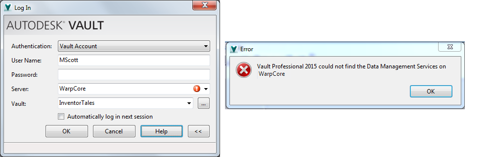
I reset IIS, the IT Admin rebooted the computer.  The same error appeared.  


I checked the standard issue things.

  • IIS?                           Running like a top
  • SQL Server?             Serving SQL just fine. 
  • Firewalls?                 Allowing traffic to pass. 
  • Log files?                  Nothing out of the norm... so it seemed....


Meanwhile, engineering has accepted a dare to use old office supplies, stale chocolate, and a 63 VW Beetle chassis to create an upgraded version of Rock 'em Sock 'em Robots.

Finally, after a bit of searching, the solution presented itself in the form of the link on the Autodesk support site here

A document came up, the first thing it said was check for the following in the Vault logs.  You'll commonly hear them called "Vlogs", and can be found using the instructions at this link.

Error: Soap Exception ( mesg-id = 635298001452597277 ) 
Exception: WebServiceError [800]
 
Exception(Inner): There was no endpoint listening at https://avia-srv3/AutodeskDM/Services/_impl/SiteService.svc that could accept the message. This is often caused by an incorrect address or SOAP action. See InnerException, if present, for more details. 
Stacktrace(Inner): 

Apparently, for reasons unknown, there was an SSL error that was preventing the connection to Vault.  I don't know all the ones and zeros that would cause this, and now with engineering trying to attach flamethrowers to their super-sized boxing game, we were focused on fixing the issue.

I try the first steps in the solution, which are:
  1. Start the Autodesk Data Management Server Console (ADMS) and go to Menu tools > Global Settings > Advanced Settings > Email.
  2. Remove the selection from the "Enable Compatibility with SSL" option.
But that doesn't solve my issue.  When I try to go to the Tools pulldown, I get the following error.


Fortunately, the solution at the link contains instructions for that case too!
  1. Use Notepad to open the web.config file from C:\Program Files\Autodesk\ADMS Professional 2014\Server\Web\Services .
  2. Change the sslRequired key from "true" to "false." 
I run these solutions, and for good measure, type IISRESET at the windows command prompt to bounce the service.

Now, both the IT admin and I hold our breaths and cross our fingers.

And then.....

It works! 

The first user logs in, then the second, and so on!  Cue epic symphonic music!

The IT admin and I congratulate each other.  If we had been in the same room, instead of working remotely, we might have hugged.

It felt like we had just successfully disarmed a bomb! 

But in the end, what's the point?  Why am I sharing this?  Will another user out in there find this helpful?

I don't know, you may never encounter this error.  And I'm the first to hope you don't.

But if this little tip resurrects just one users' Vault minutes before engineering completes their time traveling DeLorean.  If one user is able to take this and say "I was able to minimize downtime...."

If one frazzled CAD manager is just a little less frazzled, then this post did it's job!


Wednesday, December 24, 2014

How Much Can You Tolerate? - Using Tolerances Inside Autodesk Inventor Models.

“Tolerate, change, or be grateful.”
~Anonymous

The ability to create and evaluate tolerances has been around for several releases in Autodesk Inventor.  I actually can't remember when it was a "new" feature.

But it doesn't seem to get much notice.  I'm not sure how many out there know it even exists.

So I took a moment to put something together to show the steps to setup, and use, tolerances.

Before getting started, let me introduce you to the parts that are going to serve as our samples.

I've created a sample lever and shaft.  Similar to what might be seen on a carburetor butterfly valve, although it's really just a sample.

The sample for this post

With the stage set, it's time to face the next question, where to start?

The first way of adding tolerances to an Inventor model is similar to what you might do on a good, old fashioned, title block.  That step is to add tolerances per the number of decimal places as a title block.

Tolerancing in this fashion is found from Tools>Document Settings, on the Default Tolerance tab.  Here different tolerances can be set for a different number of decimal places.

Locating the Tolerance Values for a part.
For this sample component,I'm going to set tolerances as follows.
.
.00     = . +/-.015 inches
.000   =   +/- .005 inches
.0000 =   +/- .0005 inches

Adding standard tolerances.  It's almost like a title block!

Once these are set they will display on the modeling screen.  Different tolerances can be applied to different modeling dimensions by editing, and right clicking on a dimension and choosing Dimension Properties. .  Here the tolerances can be set by changing the dimension to match whatever the desired model tolerances are.


Right click and choose Dimension Properties

Setting a tolerance via a standard tolerance.

However, there are plenty of other cases where special tolerances must be used, such as deviation, limits of various types, or any other tolerance that may not fit the default tolerances for the model.

To "fine tune" tolerances by adding a special tolerance in a sketch first edit the sketch.  Once the sketch is being edited, use the same as we used before.  This time, use choose the type of dimension to be placed with the flyout.

Choosing a dimension type


If you're trying to add tolerances to dimensions for a hole feature, edit the feature, and left click on the arrow next to the dimension you wish to add a tolerance to.

Setting the tolerance on a hole feature.

Now a tolerance can be added just like the sketch dimensions.

The tolerance is set with a deviation tolerance
But what if you want to change the tolerance on something like an Extrusion or Revolution?  If you take the time to check, neither of the previous tools will work.  So how do you add a tolerance for those features?

Don't worry, there's still a way.  On the Manage tab, edit your Parameters.  All the dimensions for the part are shown here, and by choosing the arrow next to the dimension (similar to what we did in the hole feature), the tolerances for any of the dimensions driving the part can be changed.

User Parameters to set tolerance

So now tolerances have been added to the desired dimensions.... So what?  How can the limits of the tolerance be evaluated?

In each of the tolerance dialog boxes, and in the Parameters screen, there are four icons that change the size of the feature, based on the tolerance you choose.  The available options are upper, lower, median, and nominal.


For example, let's evaluate the pin and it's mating hole at it's maximum material conditions (smallest hole diameter and largest pin diameter).

To do this, edit each part in turn, and add the desired tolerances.  I'm going to use deviation tolerances, since I always found these to be the hardest ones to evaluate by hand.

After changing the tolerances in each feature, I'll set each feature to evaluate at the maximum material condition.  For the shaft, this is the upper side of the tolerance, for the hole, the minimum.

Choosing the smallest possible tolerance dimension

Choosing the maximum tolernace size for the shaft.
With these values set, I can return to the assembly level, switch to the inspect tab, and run an interference check.

Even though the parts are in tolerance, there's an interference


In this example, there is an interference that lays well within the acceptable tolerance I've created.

So what does that mean?  There's work to do?  The nominal sizes and tolernances will have to be adjusted so they don't interfere under any size that still lies within the range of the tolerances.

And what does this mean for everyone else?  

Take a look at tolerances in Inventor, and see how it can help you.  It's always cheaper to find the mistakes in the computer, than in the shop!

And finally, a couple of  "Pro Tips".

There's a couple of small tricks I learned as I worked with tolerances, so I'm going to add them here.

1. Rename parameters.  When setting tolerances, especially when using the Parameters screen. It makes it easier to know which dimensions and parameters you want to change!  There's a tip on how to do that in "Tips for Short Attention Spans".

Using named parameters

 2. Use the Document Settings "Modeling Dimension Display" to set the default dimensions for your model.  Any dimension placed will take this number of decimal places, and by default, the tolerance associated to it.


Choosing the tolerances
4, Change the precision of an individual dimension.  One option when editing a dimension's property, there's an option to change its display value.  This can make sure that you can see an accurate value for the dimension.


Changing the precision of an individual dimension


5. Use the dimension display options to your advantage.  Changing the dimension display will change how your dimensions show on the screen, and can make sure you get an accurate result.

Add caption

For example.  Using "Show Precise Value" will show exactly what the dimension's current value is.

An underline under the dimension indicates that the dimension is currently being evaluated at a value other than its nominal value.  In other words, it's set to be evaluated under one of it's tolerance values (maximum, minimum, median).


6. Explore the tools!  Many of the different tools and dialog boxes share common tools and dialog boxes.  Use that to your advantage.  You can access Document Settings from Dimension Properties for example.  You can change the Evaluated Size of a dimension from the individual dimension properties, or from  the Parameters screen, or from the Dimension Properties dialog box.

And if you've got a sketch active, you can change the dimension display from the dialog box!  Take a look!


Changing Dimension Display.

Whew!  This post did end up being a lot longer than I had planned.  But I hope you find the info valuable!


Friday, December 05, 2014

Five Quick Tips for Autodesk Inventor Assemblies

Avengers Assemble!
Marvel Comics

Over the course of the last few months, I've created tips of things that I thought others might find useful.  So far, I've created one for sketching, and part features  Now for the next step in the series, five Autodesk Inventor Assembly tips.

I've stated it in my previous tips, but I'll say it again.  These aren't in an order, of preference, just the order I jotted them down in.  Take the ones you like, and use them in any way you like!

1) Granted, this a bit of a repeat from part modeling, but this tip works well assemblies as well.  And that's the "Select Other" tool.

When assembling components, Inventor allows us to rotate components while adding constraints, I use this all the time, especially with my 3DConnexion device.

However, there are plenty of times that I don't want to rotate the parts when adding constraints, and this is where select other can come in real handy.


2) Other times when adding constraints, I need to place a lot of constraints quickly.  This is particularly true of insert constraints.

Inventor has another way of placing constraints that has been around as long as I can remember, but seems to have been lost over time.

That method is the Alt+Drag method.

In short, select the geometry to be constrained while pressing the "Alt" key, and the appropriate constraint can be selected.  Drag the constraint to the mating part, release the Alt key, and the constraint is placed.  All done without touching the constraint icon.

The act of using Alt+Drag

It's not a big time saver for a few constraints, but when placing several, it starts to add up.

There's more information from my earlier blog post here! 

3) Another tip I picked up over the last few years came from users who worked with a lot of sheet metal.  It's a creative use of the Flush constraint.

When selecting a small edge to be mated to another, it can be difficult to get the desired face.  Mate, being as flexible as it is, can start picking edges and points near the edge of the face.  It makes it tricky to get what you want.

One option is to use the Select Other tool, just like I mentioned in Step 1, but there's another approach that I think might help everyone out.

That approach is the Flush constraint only see faces.  Starting with that as a constraint, will easily pick the face.  All that is left to do is switch it to Mate once the face is selected.

This can be a huge time, and patience!


Here's a tip on using a flush constraint to pick a narrow face

4) This one has happened to me more times than I want to admit. I've started out with two parts that I swear are totally identical.  I have those components constrained into place, and everything is just about set....

Then I realize that there's one feature that makes one instance of the part different from the other...

Classic.  Two parts I thought were the same, and I realize they're not when they're already placed.

Fortunately, there's a tool called Save and Replace Component.  It's located on the Productivity flyout, and it's perfect for exactly this situation.

Locating the Save and Replace Component tool.
Save and Replace Component creates a brand new copy of the existing part, and swaps the new part for the old.

The bonus?  No constraints are lost, and you can quickly make the changes that make the part unique!

The result with very little inconvenience! 


5) Finishing up the assembly tips, one last one is a tip for a set of features introduced in Inventor 2014, but might have gotten lost in the forest that's created by so many new features.

It's not available in 2013 or earlier, so sorry for those on the older versions.

All of these sets are from the same group, so I'm combining them in together as a "super tip".

First, is to drag a part using the Free Move command.

In previous releases, this just moved the part away from the assembly, regardless of constraints.  But now it shows "bands" between the moved part, and the components it's constrained to.  It's a visual map to how the constraints are behaving. This also includes glyphs showing you what type of constraints are in use.  Right clicking on the glyphs lets you edit, modify, modify, and delete constraints.

Using the Free Move command to show constraint relationships

The other tools are on the Relationships tab.  They're Show constraints, Show Sick constraints, and Hide All constraints.  The name says it all.

Show constraints displays the constraint glyphs for a component that you select.

Showing Constraint Glyphs

Show Sick constraints will show constraints that have conflicts with other constraints.\

Showing Sick Constraints


Hide All constraints turns off all the glyphs.

Hiding All Constraints


I know I've grown to like these tools as I've used them, but it can be easy to overlook them.

So if you've been upgrading and forgot about these tools, take a look!

And I know.  There isn't a video for this one.  Things have kept me rolling where I haven't quite been able to create videos.  I'm hoping that things might just wind down enough where I hope to create one soon!

****Edit 31-December-2014****

At long last, I had the time to create a video to accompany this post!  Take a look!  I hope you find it helpful!

And Happy 2015!


Sunday, November 30, 2014

CAD Programs as Tools. CAD Drafting as a Trade.

This post was inspired by random internet searching, and stumbling onto an interview with Mike Rowe of Dirty jobs, that really made me spend quite a bit of time contemplating things.  It even caused me to search around more for more articles.

Here is the video.  It's about 40 minutes long, but I found it fascinating.


So what is the point of this?  Does this even apply to those using CAD?  Is Jon just rambling on?

Mike Rowe said one thing that struck me.  "I do believe, whatever your job is, if you approach it like a trade, you'll be better for it."

Now, like Mike Rowe, this isn't me attempting to bash higher education.  I have a Bachelor of Science in Mechanical Engineering, and I wouldn't trade that for the world.  I'm proud of that.

But on the other hand, my father made a living with a wrench in his hand.  He crewed and worked on aircraft in the U.S. Navy.  After that he was a certified Airframe and Powerplant mechanic for Western Airlines, and finally McDonnell Douglas.

He was a tradesman, and a very good one at that.

The Avenger.  My father worked on these in the 1950s. 

My father in the early 1990s.
He wrapped up his career working on MD-80s

And I've been fortunate enough to have him as a mentor, and many like him.  I've been lucky enough to be mentored by woodworkers, machinists, and aircraft mechanics.  I've learned to respect the skilled workers who create with their hands.

Of course every one of these skilled workers has their tools.  The implements that are more than just what their mass and volume represent.  They're an extension of a workers hands, a way of making a living.

Thinking about that a moment, isn't CAD a tool?  As designers using CAD, isn't that the extension of our hands?

When it comes right down to it, is a CAD program, be it, AutoCAD, Autodesk Inventor, Dassault Solidworks, Revit, CATIA, ProEngineer, and so on.  Aren't they our tools?

Autodesk Inventor, laptop, and 3DConnexion 3D mouse.
Are they different than the wrench and rivet gun?
Or different tools for a different trade? 

And since these are the tools of our trade, shouldn't we be trying to use them to the best we can, to hone our craft and get the most we can out of them?

Does that mean you need to go and call your reseller and buy thousands of dollars of custom training?  Maybe. That would make your account manager very happy, but sometimes we're not able to do that.

Does that mean you seal yourself in your basement, and spend hours upon hours honing your skills on the product of your choosing?  Perhaps.  But that's not something everyone is able to do.  There are commitments and family, and time is valuable.

What it means to me, at least, is to find what makes me better.  From a CAD perspective, that means I spend time looking at articles from some great sources.

I would also love to attend Autodesk University every year.  But alas, that one isn't in the cards for me, at least not this time.

Why?  I learn things I don't know, it teaches me to look at problems from different angles.  It encourages me to try new things I may not have thought of.

I've also started taking Aircraft Maintenance Classes at Mount San Antonio College.  Someday, I could learn enough to earn my own Airframe and Powerplant license, although it's going to take me a long time.

A sheet metal practice plate I used to practice riveting in class.
It takes practice to learn this skill! 
I also volunteer at Planes of Fame in Chino, Ca.   I'm lucky enough to help recover fabric control surfaces there, and see aircraft mechanics who have become so skilled with their trade, they've crossed into a realm that has become pure artistry.

A iron in the foreground.  It was used on the rudder (laying on its side in the background) to
heat shrink the fabric used in the process.  These are the tools of the fabric trade. 
Why?  It keeps my hands dirty.  I get to understand why something is done and how things go together.  I learn the things that can't always be learned by reading manuals and watching videos, or even sitting in a classroom.

Does that mean that this is your formula?   Should you go read blogs galore, take classes.  Is this how you "think like a freelancer" as Mike Rowe put it?

No, it doesn't.  It represents the choices I've made on how to improve how I use my tools.  It's how I sharpen my own freelance.

If anything, you should find your own resources, your own way of learning how to increase your knowledge, and improve your skills.

Ultimately, it's a choice we're all faced with making.  And every choice, including choosing not to decide, is making a choice.

Oh, and is using CAD, any CAD, a trade?

In my opinion?  There's no doubt the answer is yes.


Tuesday, November 25, 2014

A Use for Inventor's Sketch Constraint "Relax" Mode

“Try to relax and enjoy the crisis.”
 Ashleigh Brilliant 

Sometimes, it takes the right circumstances to find a good way to use a new feature in Autodesk Inventor.

The new Relax mode in Inventor 2015 fell squarely into this bucket.

When it first came out, I was frankly a little unsure of the new tool.  It's my nature.  I just find myself wary of any tool that is "too automatic".  I'm just type "A" enough to not like it when too much is done for me.  I circle them like a cat sizing up a potential meal.

But I've also learned that there is a time and a place for these tools too.  Experience has taught me to never dismiss a new function too quickly.

In my case, I was rebuilding an aircraft instrument panel in Inventor.

Originally, I had created it as a test to benchmark how text affected the speed and file size in Inventor.  To do this, this, I created the cutouts for the instruments as extruded borders with text inside.

A sample of the original panel.  There were no cutouts for instruments,
but this was part of a test and not meant to be "real" at this point.
Not accurate as a part.  But perfect for the benchmark I was creating!

But once I had done that, I wanted to create a more accurate representation of the panel.  This meant deleting the extruded  borders, and recreating them as cutouts.

But as I did that, I ran into one issue.  Part of the sketch that I had removed had anchored the text that I had placed.  Now the geometry was disassociated.


I could delete and recreate the sketch, but I didn't want to try to retype all that info again.

But what I did find was able to delete constraints to free the geometry and reattach it to other geometry,  In some cases, this meant deleting four co-linear constraints, and recreating them all over again.  This is what I would have to do with these circuit breaker cutouts, for example.


While it wasn't a huge pain for a few of them, there were a ton, there was a lot to do, so how could I make this task go a little quicker?

Well, if you guessed that I used the "Relax" constraints mode that's new to Inventor 2015, you would be guessing correctly!

First, while editing the sketch in question, I  turned on Relax Mode,  It can be found at the status bar on the bottom of the Inventor drawing screen.  You can also use the hotkey "F11"


Once that was on, all I had to do was grab the text and drag it.  The constraints would automatically be removed, and I apply the new sketch constraints right away.


Is it a small thing?  Perhaps.  But over time, it did make fixing the panel a lot easier!

A simple thing?  Perhaps.  But it can be the simple things that matter.


Thursday, November 13, 2014

Did You Know You Can Use the End of Part Marker to "Compress" an Inventor File

“The question is, what's the best way to do this? There may not be a one-size solution to the question.”
 Peter Gore

Today I wrapped up some basic benchmarks for extruded text versus sketched text in an Autodesk Inventor part model, and I was getting ready to e-mail them out for some testing on external systems.

First, what did I use for the test?

The files I created were from an instrument panel for light sport aircraft from the RV series.

I recreated the panel from an image, and created the instrument identification first as extruded text.

The panel with extruded text

In the next panel, I created a panel with the same text, but this time, the panel the text was created as sketches, and not extruded into 3D extrusions.

The panel with sketched text.  You can tell by the projected sketch lines, which are magenta.

The challenge?  The panel with the extruded text was nearly 13 MB!

12.7 MB.  That's big! 
By comparison, the panel using just sketches was less than 2 MB!

1.64 MB.  Nearly a tenth the size!

First, let's take a moment to ponder that.  If you're creating a lot of text, consider leaving it as sketches. These two models show a big difference in the size, and that can affect performance, especially if there's a lot of them.

But there was also another challenge I was facing.  How can I e-mail the files?  Together, these files are flirting with 15 MB.  That's big enough to cause problems with some e-mail systems.

Sure, I could zip the files, but there's another way to "compress" an Inventor file.

Locate the End of Part marker.  It's also known as End of Folded if you're using a sheet metal part.

Right click on the marker and choose Move EOP to Top (or  Move EOF to Top for sheet metal parts).

Locate the End of Part marker.
This pushes the marker to the top, and all the a feature in the part are suppressed.

The EOP at the top, and the features suppressed
After compression, the part with extruded text was a mere 2.41 MB.

A big change from 12.7 MB

By comparison the panel using Sketches was 1.01 MB.  Not as drastic as the larger file, but substantial nonetheless.


A smaller change, but still about a third. 
Having that trick can make it much easier when moving large part files back and forth.

When the recipient gets the file on the other end, just right click on the EOP/EOF marker and choose Move EOP/EOF to End.

How to get it back. 
This can be a nice way to "compress" an Inventor file without having to use zip files.  So when you're sending part files around, take a look!  It's worth a glance.

Oh!, And if you have an unsuspecting coworker, rolling the EOP to the top of their part when they leave their computer unattended has been known to be an "April Fools Trick" in the past.

Not that I condone that..... Or I've ever done that....

*************************Edit 17-November-2014*************************

Thanks to Clint Brown of Cadline Community for sharing a nice bit of iLogic code that will rollup the EOP marker and put it in an email for you.

It's definitely work taking a look at!

Have a look by clicking here!