Find us on Google+ Inventor Tales

Wednesday, November 29, 2017

Lessons From Life's Workbench - The Blind Rivet

Over the last few weeks, I've mentioned how solid rivets are sized by part number and selected for diameter and length.

Solid rivets joining two pieces of
aluminum together. 
Solid rivets are amazing little pieces of metal.  They've been used in aircraft for decades, and if you've flown on an airplane, the odds are you've been depending on these little pieces of metal to ensure your safe flight.

And while these pieces are amazing in both their simplicity and effectiveness, like anything, they are not without their drawbacks.

They're inexpensive, but they require a certain amount of skill to properly set.  Proper riveting takes practice, and I found if I don't do it for a while, I have to shoot a few practice rivets to get "back into the groove." 

The other problem is access to both sides of the part are required.  The rivet has to be "shot" with a tool from one side of the part, and "bucked" or set, from the other.

If you're curious about seeing how solid rivets are set, the Experimental Aircraft Association has a great video explaining that here!

Moreso, it's likely that one person won't be able to reach both sides of the parts to be joined.  That means that two people are needed to set the rivet, a "bucker" and a "shooter".

Two workers setting solid rivets.
If you take a couple of moments to think about that, what you have is a rivet that maybe inexpensive, the workers required to place will be where the expenses will be found.

The blind rivet, also known as a "pop" rivet or "Cherry-Max" rivet solves both of these issues.  'For trivia's sake, the name "Cherry-Max" is derived from Cherry Aerospace, a prominent maker of  blind fasteners.

These rivets have a metal stem (mandrel) that is drawn through the rivet by a special tool.  The metal stem expands the rivet as it's pulled expanding the rivet and setting it in place.  The stem breaks off inside the rivet, adding to the rivets strength.

A blind rivet diagram.  Image from FAA Advisory Circular
AC43.13-1Bhttps://www.faa.gov/documentLibrary/media/Advisory_Circular/AC43.13-1b.pdf


The advantage of these rivets is they don't require the skill that a solid rivet requires. They also don't require that the part be accessible from both sides.   The drawback of these rivets is they are much more expensive than their solid counterparts.
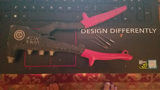
A blind rivet tool, with unset blind rivets under the
"Design Differently" sticker on my laptop.
So like in so many cases in design and manufacturing, a benefit isn't seen without making a concession somewhere else.  So when all is said and done, you can still find both types of rivets in widespread use.

If you're curious about how to set blind rivets, here's a link to a great video here.

For more information on selecting blind rivets, check out the process guide  provided by Cherry Aerospace at the link here.

I  leave it to them to provide the info for you!   Mostly because I have to review it myself to refresh in my own memory!

But there you have a few of the "wheres and whys" of rivets.  I hope the info I've compiled here helps you out!

Photo Acknowledgements:

photo credit: The Library of Congress Riveting team working on the cockpit shell of a B-25 [i.e. C-47] bomber at the plant of North American Aviation, Inc., Inglewood [i.e. Douglas Aircraft Company, Long Beach], Calif.   (LOC) via photopin (license)

Sunday, November 26, 2017

A Quick Tip on Creating a New Drawing in Fusion 360

The Thanksgiving Holiday here in the United States and some studying for a class have been keeping me busy, but I've been starting to get a little seat time creating drawings in Fusion 360 for a wooden rack I've been working on.  
The Fabric Rack in it's current state.
There's still some adjusting to be done! 
The tip I'll share is a simple one, but one that not everyone may realize is there.  

I know I haven't been using this tool nearly as much as I should have! 

If you right click on a component in the model tree, you can create a drawing for that component by choosing Create Drawing

Creating a drawing from the model.


Choosing that option, a dialog box appears that gives the following options. 

1. Create a drawing of the full assembly found in the model, or just selected components in the model. 
The first step to creating a drawing

2. Create a new drawing from the selected component(s), or add a component to an existing drawing. 

3. Choose a template drawing or start from scratch. 

4. Choose to use the ASME or ISO drawing standard.

5. Choose the default units for the drawing.

6. And finally, choose the sheet size for the drawing.  

Once you hit OK, the drawing will generate and you'll the opportunity to place the views on the darwing.  These options include

1. View Orientation

2. View Style, such as Visible Edges, Visible and Hidden Edges, Shaded, or Shaded with Hidden Edges.

3. Scale so you can size the view to the page.

4. Tangent Style, which include Full Length, Foreshortened, and Off. 

5. Toggle Interference Edges on or off. 

6. Toggle thread display on or off.

I found it can be a slick way of creating a view, some of which I'm still testing out!  But I think it's well worth taking a deeper look!  

I'll keep you posted! 


Thursday, November 23, 2017

Lessons from Life's Workbench - Penetrant Inspection

Happy Thanksgiving to those in the United States.  Enjoy the holiday!  Here's a quick post on penetrant inspection for your consideration! 

In my aircraft maintenance classes, I've been able to try my hand at dye penetrant inspection.  
An example of cracks in a part.  This is actually from
magnetic particle inspection test.  But the tests are similar,
and it's the best picture I have! 

There are a few variations of the process, but the one I performed soaked the part in an light oil containing a phosphorescent dye.  

The dye soaks into cracks and voids in the material.  After soaking, the part is rinsed to remove penetrant on the surface of the part, and finally, it's sprayed with a powder like developer to draw some of the remaining penetrant out of the flaws so they can be seen with a UV light.  

After inspection, the part is thoroughly cleaned and returned to service, assuming it passed inspection of course.  

It's a quick, fairly easy to perform test, and can be a great to find surface flaws on a part.  

It's also messy, at least where I learned how to do it!  But a little mess never hurt anyone. 

But my experience, isn't vast by any means.  It's something I've tried enough to gain some familiarity with.  

For a little more information, check out these resources.  


Wednesday, November 15, 2017

Lessons From Life's Workbench - Intergranular Corrosion

One of the most insidious types of corrosion I learned about in my classes is intergranular corrosion.  Aluminum alloys containing copper, such as 2024 aluminum, particularly if it's been improperly heat treated.  

The copper in the alloy comes out of the solution, and creates tiny galvanic cells that begin corroding the metal. 

The sneaky part of this type of corrosion is that it can happen deep inside the material, and may not become visible until the corrosion breaks the surface of the material in a process called exfoliation. 

 
Here are some pictures of aluminum that has some serious exfoliation.
The metal has completely disintegrated.
Another angle of the same extrusion.
You can see how the material has flaked away.
It goes without saying that intergranular corrosion is bad.  But if it can start in the interior of a material, where it can't be seen,, how can it be found?

That's where nondestructive tests (NDT) such as ultrasonic inspection or eddy current inspection can be employed to locate and eliminate this type of corrosion before it affects the strength of the structure. 

That's it for this weeks tip!  Have a great week!