
Kathleen Sebelius
Sitting in my hotel room on a business trip to Dallas, Texas, I found myself taking a look at a new feature in Autodesk Inventor 2014, and thought I would go ahead and create a short post on it.
This new feature is "Show Relationship" in an assembly.
Activating this feature shows the relationships between constraints in the modeling window, in a graphical format.
For this example, I'll use the Craftsman style coffee table I've used dozens of time before.
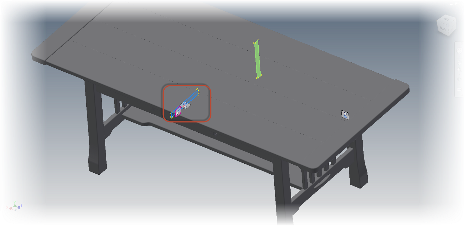 |
| The constraint relationship glyphs showing on the Craftsman Style Table |
By using a graphical representation, the constraint can be easier to visualize, modify, and delete.
The first step to using the relationship is to show them. This is located on the Assemble Tab by clicking the Show icon.
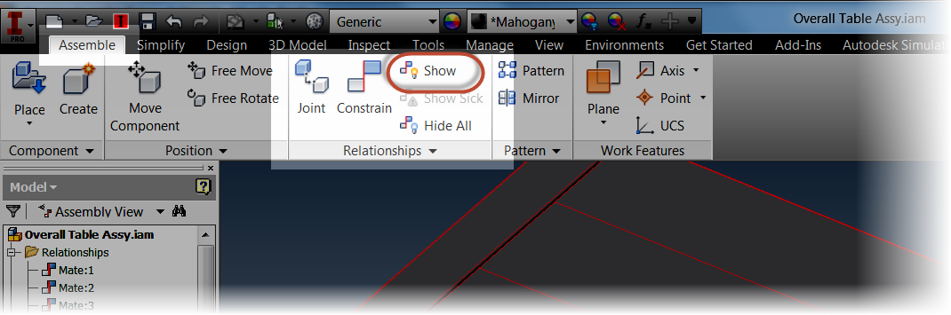 |
| The Show Relationships tool |
Once the icon is selected, I can choose the components I want to show the relationships for. In this case, I'm just going to look at the table top.
Glyphs will appear where the constraints between the table top and the lower table it's connected to.
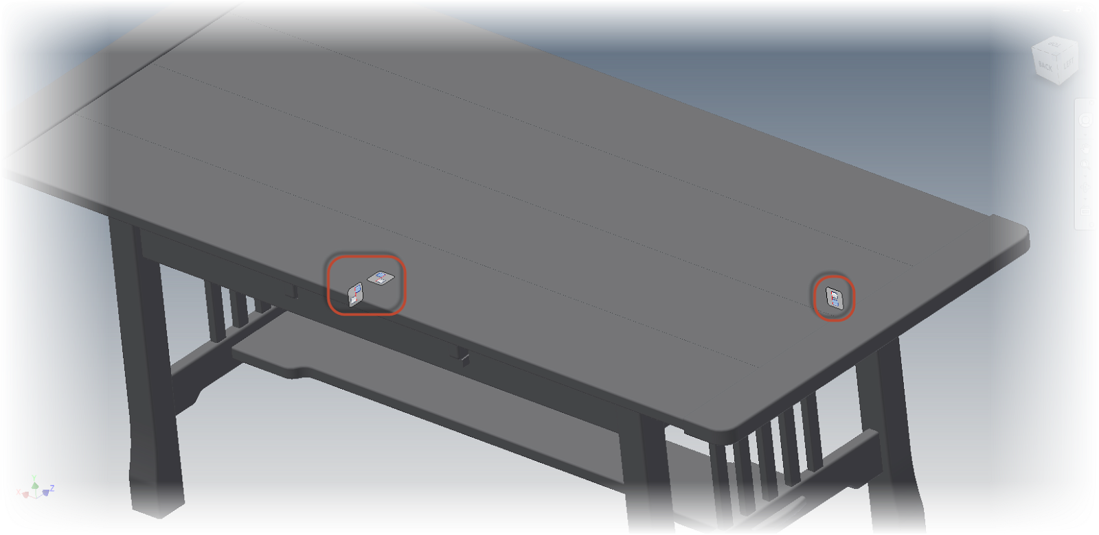 |
| The Constraint Relationship glyphs |
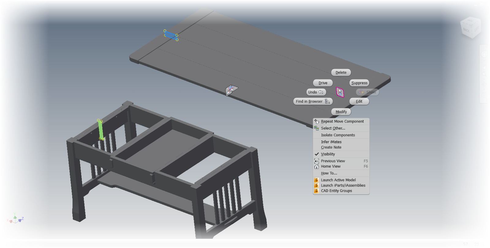
Right clicking on the constraint glyphs provides the operations that can be performed on this constraint, such as, Edit, Delete, and Suppress, among more.
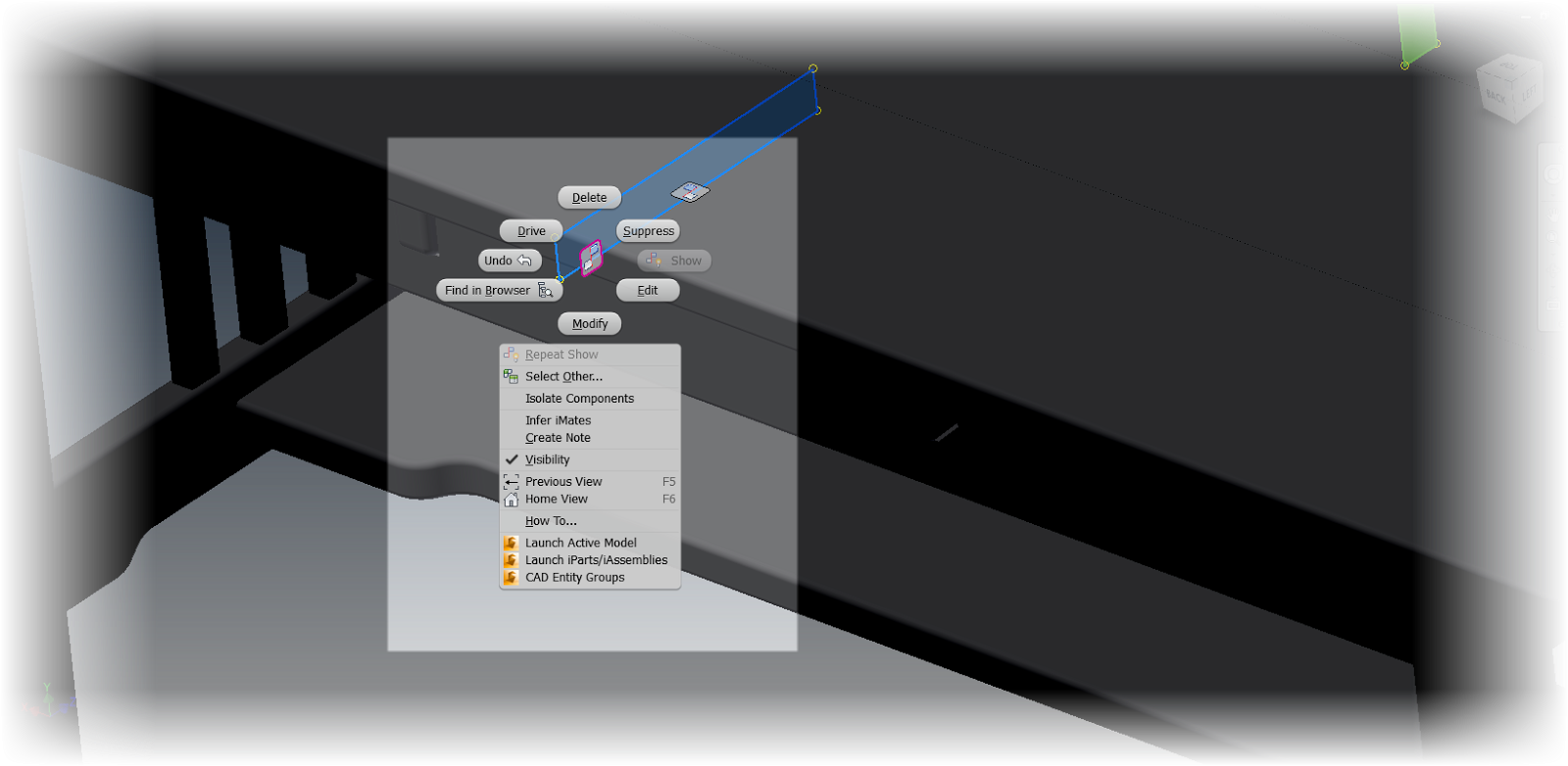 |
| Right clicking on a glyph will show the editing tools |
If the component is moved using the Free Move command, "bands" appear that connect the constraint to its mating components while the command is active. After this I can right click and choose "OK" to complete the move.
 |
| Using the Free Move command to separate components |
Clicking on the constraint will also highlight the geometry that the constraint is attached to, giving a quick graphical way of seeing how the constraint is being used to constrain the geometry. Just like before, right clicking on a constraint will show the options for that constraint
 |
| The components move apart, showing the right click options |
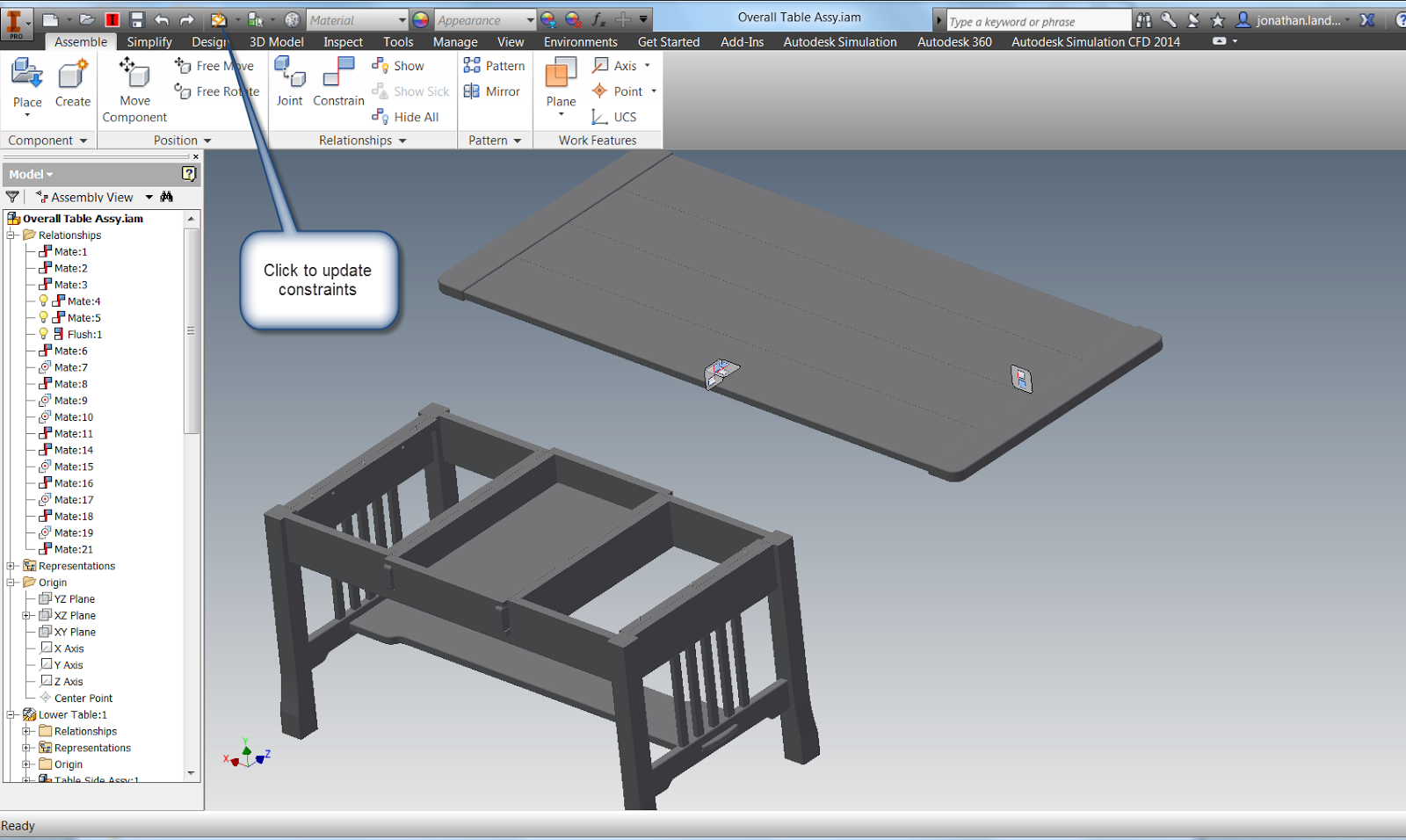 |
| Updating the assembly will restore the constraints |
But before I say "take this tool for a spin", there is on other place this tool can help out.
If there are "sick" constraints, such as conflicting constraints, can be graphically diagnosed using the Show Sick Relationships tool.
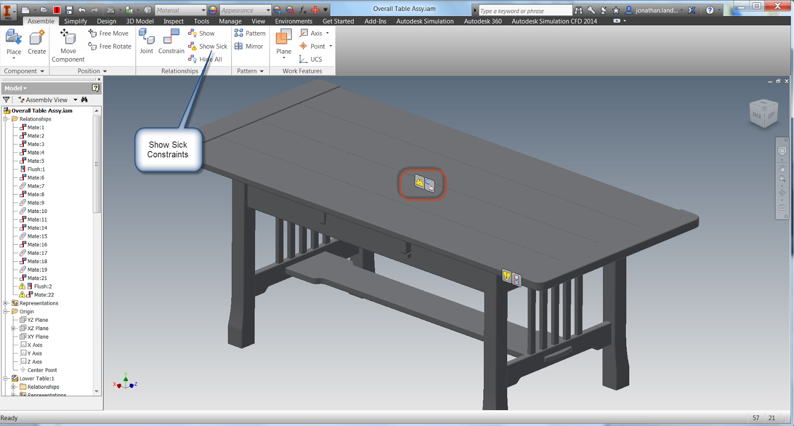 |
| Showing Sick Constraint Relationship for diagnostic purposes. |
With this ability, the Show tool can be used for editing, and for diagnostics!
So on that note, take this tool for a spin! And in addition, here's a video on the subject!
Always Nice Video You publish
ReplyDeleteJohan
Thank you, Johan. Your kind words mean a lot!
Delete